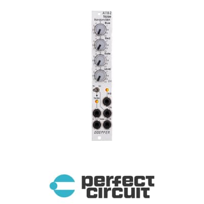
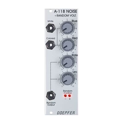
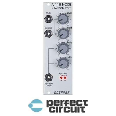
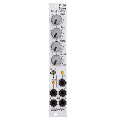
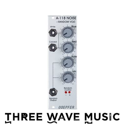
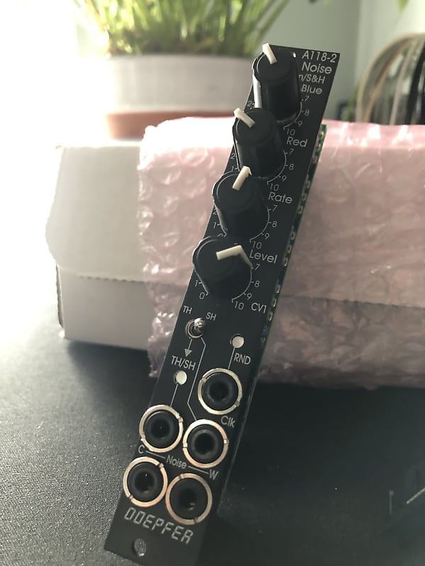
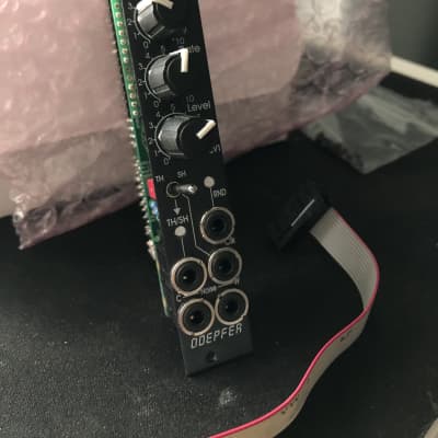
DOEPFER A-118-2V
Combining white and colored noise with continuously variable random and stepped random voltages, the A-118-2V from Doepfer is a compact source of randomness. Noise comes in both white, which is flat in its energy distribution, and colored which is skewed to the higher or lower frequencies, depending on the blue and red knob settings. In general terms, blue noise is high frequency noise, while red noise is low frequency noise. The level of each of these components is controlled by their respective knobs which controls the overall timbre of the colored noise output. The RND or continuous random voltage is derived from the colored noise with the assistance of a low pass filter that turns the noise into a smoothly fluctuating random voltage source. The settings of the blue and red noise influence the behavior of the fluctuating random voltage. The level and rate of this changing voltage can be set with the level and rate controls. This is also passed into the T+H/S+H section, which stands for "track and hold" and "sample and hold". When used as a T+H, the output follows the level of the incoming voltage as long as the incoming gate signal is high. In S+H mode, the rising edge of a signal such as a gate or square wave causes the S+H to look at the voltage level and take a snapshot, capturing that voltage level at the time the clocking signal goes from high to low. This voltage level is held until it receives another clock signal. The S+H and T+H are intended to be used with signals with a hard rising edge such as gates and square wave LFOs. This little module brings together the essential building blocks of a random voltage source complete with noise, fluctuating random voltages, and stepped random voltages, that adds a bit of unpredictability to your patches.
A-118-2V FEATURES
- Random voltage and noise source
- White and colored noise outputs with controls for high and low frequency noise
- Continuous fluctuating random voltage derived from the colored noise output with rate and level controls
- Track and hold lets all voltages through when a gate is present
- Sample and hold takes a snapshot of the voltage level present at the input and outputs it when it receives a clock signal