Doepfer A-118-2: Noise and Random
This seller has not set a shipping cost for Slovenia. Please contact them to ask about shipping.

14-Day Return Policy
Enjoy peace of mind with your new gear
Our users rate Reverb
MAY NOT COME WITH BOX
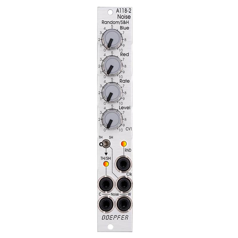
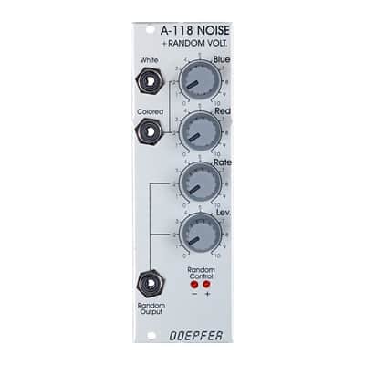
Module A-118-2 is the slim version of module and offers essentially the same features as the . But the distances between the controls are smaller and rubberized small-sized knobs are used. In return the front panel has 4 HP only which is half the width of the . The module is primarily planned for applications where only limited space is available. The functional difference between A-118-1 and A-118-2 is the additional T&H/S&H unit which is not included in the A-118-1.
The module generates the signals white noise, colored noise, continuous random voltage and stepped random voltage (derived from the continuous random voltage by means of a S&H/T&H unit).
The noise signal is generated 100% analog by amplification of the noise of a transistor. White and colored noise are usually used as audio sources. The random voltages are normally used as control voltages (e.g. for filter frequency or any other voltage controlled parameter).
The A-118-2 gives you the ability to mix the relative amounts of Red (low frequency component) and Blue noise (high frequency component) in the colored noise output.
For the continuous random voltage the rate of change (Rate) and amplitude (Level) of the random voltage can be adjusted. The continuous random voltage is derived from the colored noise signal by low pass filtering. Consequently the settings of the controls for the colored noise (Blue, Red) affect the behaviour of the random voltage ! A dual color LED (red = positive / yellow = negative output voltage) indicates the continuous random voltage.
The continuous random voltage is used as source for the S&H/T&H unit. The type of operation can be set to S&H (sample and hold) or T&H (track and hold). When T&H is chosen the output signal follows the input signal (= continuous random voltage) as long as the Clock input is "high". As soon as the clock signal changes to "low" the last voltage is stored. When S&H is chosen the input signal (= continuous random voltage) is sampled at the rising edge of the Clock signal.
For the Clock signal a "digital" signal (e.g. Clock, Gate, rectangle output of an LFO) is required. It does not work with slowly changing continuous CV signals. Another dual color LED (red = positive / yellow = negative output voltage) indicates the stepped random voltage.
Controls:
- Blue: share of the high frequencies in the the colored noise output
- Red: share of the low frequencies in the the colored noise output
- Rate: rate of change of the continuous random voltage
- Level: amplitude of the continuous random voltage
- TH/SH: switches between T&H und S&H
Inputs and outputs:
- RND: continuous random voltage output (with LED display)
- TH/SH: stepped random voltage output (with LED display)
- Clk: Clock input of the S&H/T&H unit
- C Noise: colored noise output
- W Noise: white noise output
Important notes:
After power on it takes a few minutes until the two noise signals and the random signals are generated. The module is not faulty when after power on the signals do not appear immediately !
The S&H/T&H function is realized by pure analog circuitry (electronic switch followed by a holding capacitor and buffer). Consequently the output voltage drifts a bit in the holding state because the capacitor is discharged by parasitic resistors. The drift depends also upon environmental conditions like humidity or temperature.
| Condition | Brand New (New) Brand New items are sold by an authorized dealer or original builder and include all original packaging.Learn more |
|---|---|
| Brand | |
| Model |
|
| Categories | |
| Horizontal Pitch |
|
| Synth Module Function |
|
| Modular Synth Format |
|
Product safety information may be available here.