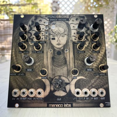
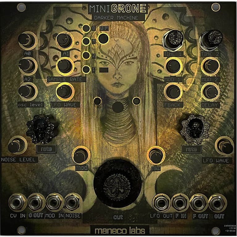
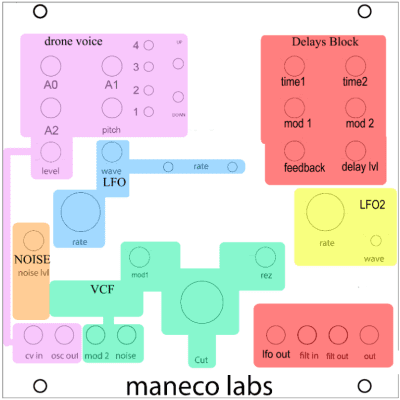
Blocks description
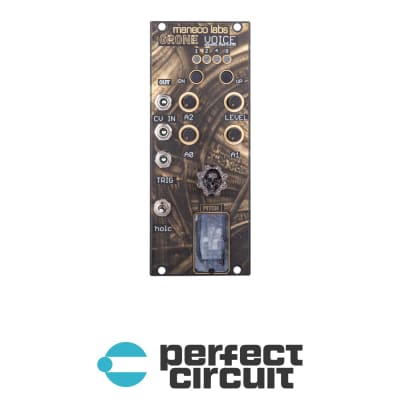
Drone VCO :
Generates sound based on equations converted to analog signals , there are sixteen equations
selected by Up and Down switches. Four leds indicate equation number in binary mode. Three
Pots modify numbers used by the equation, A0 , A1 and A2 , fourth pot Sample Rate controls
pitch and speed of the oscillation. There’s an Output Level pot for the oscillator and a dedicated jack for patching the Oscillator sound to external modules .
NOISE GENERATOR : White noise with noise level pot and noise output jack.
VCF : MS20 resonant low pass filter , with CUT frequency pot control , RESONANCE ,
MODULATION 1 amount pot , input and output jacks and second cv input for cut off ,labeled
MOD2
LFO 1 : Low frequency oscillator routed to MOD1 from VCF , RATE and WAVEFORM shape
Pots.
Also routed to delay block 1
Waveforms are : ramp up, ramp down, square, triangle, sine , sweep, random levels, random
slopes
LFO 2 : Low frequency oscillator routed to delay block 2, RATE and WAVEFORM shape
Pots.
Waveforms are : ramp up, ramp down, square, triangle, sine , sweep, random levels, random
Slopes
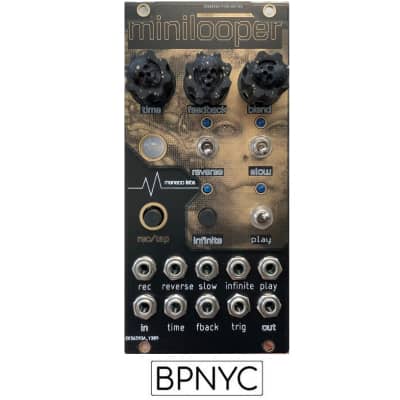
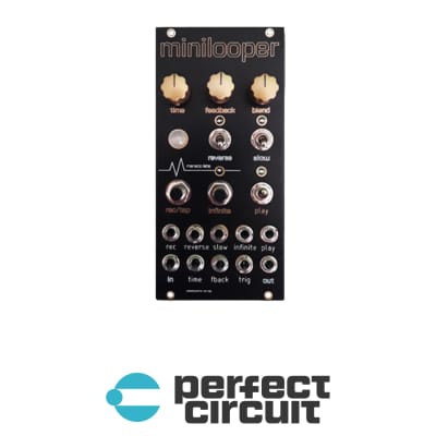
DELAYS BLOCK:
2 delay lines in parallel sharing feedback and blend controls.
Time 1 and mod 1 control delay block 1 , time 2 and mod 2 control delay block 2