Doepfer A-143-2 Quad ADSR
Price$255
Free Shipping
Free Shipping
from Burbank, CA
Listed:over a month ago
Views:1542
Watchers:33

Burbank, CA, United States
Free Shipping
from Burbank, CA
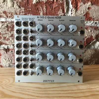
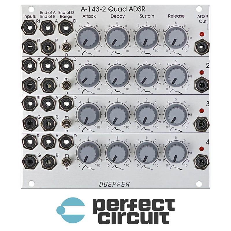
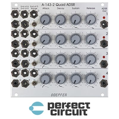
The A-143 series of modules contain multiple modulation sources. Module A-143-2 is a four-fold ADSR type envelope generator.
The module contains 4 independent ADSR-type envelope generators. Each sub-module has available the controls Attack, Decay, Sustain and Release. The three-position Range switch allows to select the desired time range (low - high - medium). The adjustable envelope time ranges from several minutes to some milliseconds. On top of this each sub-module is equipped with three digital outputs (high/low): "End of Attack (EOA)", "End of Decay (EOD)" and "End of Release (EOR)". As soon as the criterion is valid (e.g. end of decay state) the corresponding digital outputs turns to "high". These outputs can be used e.g. to daisy-chain several ADSR sub-modules. For this the digital output in question (EOA, EOD or EOR) has to be connected to the Gate input of the following ADSR. Even automatically running envelopes (pseudo LFOs) or so-called "quadrature envelopes" with cyclical modulations of several ring-shaped, daisy-chained ADSRs are possible. To obtain a pseudo LFO simply the EOD or EOR output has to be connected to the Gate input of the same ADSR.
In addition to the obligatory Gate (G) input for envelope generators each sub-module has available a Retrigger (Rt) input. The retrigger turns the direction to "upward" if the envelope has already reached the decay state while the retrigger pulse occurs. If the envelope is still in the attack phase the retrigger input has no meaning. This a different behaviour from A-140 and A-141 !The Gate inputs of the units 2, 3 and 4 are normalled to the Gate input of unit 1, i.e. Gate input 1 is connected to the switching contacts of the Gate input sockets 2, 3 and 4. Thus one Gate signal applied to Gate input 1 can be used to trigger all four sub-modules simultaneously.
The envelope outputs are displayed with LEDs. The maximal envelope voltage (Attack/Decay reversal point) is about +8V.
Features
| Condition | |
| Brand | |
| Model |
|
| Categories | |
| Horizontal Pitch |
|
| Synth Module Function |
|
| Modular Synth Format |
|