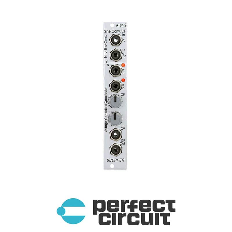
Doepfer A-184-2 VC Crossfader

30-Day Return Policy
Enjoy peace of mind with your new gear
Our users rate Reverb
The upper section is a very precise triangle-to-sine converter (thank's to Tim Stinchcombe who recommended this circuit). It can be used to convert any triangle waveform into a (nearly) perfect sine. The converter is much better than the simple diode converter used in the A-110-1, A-111-1, A-145 and A-147-2. Two trimming potentiometers are used to optimize the sine shape. The converter should be assigned to one VCO or LFO because the trimming potentiometers have to be re-adjusted if the input level or DC offset of the input signal changes. If the trimming potentiometers are deliberately mis-adjusted it can be used also as a waveshaper for non-sine waveforms (e.g. sine-shaped at the top of the signal and a peak at the bottom, even voltage controlled by applying an additional voltage to the waveshaping circuit, "circuit-bending" notes will be available).
The lower section is a voltage controlled crossfader. It has two inputs A and B. The two signals are mixed together with variable percentage. When the manual control CF is fully CCW only signal A appears at the CF Out socket. When the manual control CF is fully CW only signal B appears at the CF Out socket. In the center position of the manual control both signal appear with the same level. In addition a control voltage input CV with attenuator is available to enable voltage control of the crossfade. Two LEDs display the crossfading shares of input A and B. The crossfader uses two high quality VCAs (SSM2164). Inputs and outputs are DC coupled. Consequently it can be used for audio signals and slowly varying control voltages as well.
| Condition | Brand New (New) Brand New items are sold by an authorized dealer or original builder and include all original packaging.Learn more |
|---|---|
| Brand | |
| Model |
|
| Finish |
|
| Categories | |
| Synth Module Function |
|
| Horizontal Pitch |
|
| Modular Synth Format |
|
Product safety information may be available here.