Once you start playing guitar, it doesn't take long to figure out what you like and don't like in an instrument and to develop your own ideal specs. However, we all know that commissioning a custom build isn't always in the budget.
Building a partscaster guitar can be a great way to compromise—get the guitar you've always wanted for a price you can afford and learn some great skills in the process.
In our video above, Andy Martin explains what you should know before building your very first partscaster. And below, we're going to run through some of the key processes, from matching the body to the neck to tips and tricks for achieving the perfect finish.
- Parts Brands: Allparts, Mighty Mite, Warmoth
- Parts Shops on Reverb: The STRATosphere, MJT Custom Aged Guitar Finishes, Tricked Out Guitar, Gunstreet Wiring, StewMac, Mojotone
- Guitars: Redtail Guitars
Establishing a Centerline and Preparing to Connect a Guitar Neck and Body
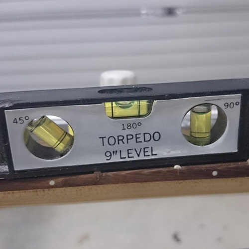
In a perfect world, your neck and body would be an immediate fit. But chances are, the neck is going to be either too wide or too narrow for the neck pocket. In either case, the first step in the fix is establishing the guitar’s centerline, which will require the following tools:
- Straight edge
- Protractor and drafting square
- Erasable marker
- Accurate ruler or Vernier calipers
The depth of the neck heel should be a major consideration when selecting a neck. While minor adjustments can be accomplished when setting up the guitar’s action, for major depth and tilt issues, seek professional help. The heel base is a hyper-critical element of a solid-playing guitar. We can, however, address the heel width.
If Your Guitar Neck Is Too Wide for the Neck Pocket
Reducing the heel width of a guitar neck requires specialist tools and a full-length trim on both sides of the neck, so that’s a luthier’s job. But for basement and garage builders, modifying the neck pocket is your best and easiest option.
How to Plot the Centerline
Let's walk through measuring, marking, and cutting to increase the width of the neck pocket on both sides, which first requires establishing and then maintaining the guitar’s centerline—which is necessary to ensure that the nut, neck, and bridge are in alignment.
- Measure the nut width and divide by two.
- Mark this point on the nut between 3rd and 4th string slot.
- Repeat at 12th and 21st fret, confirm the line between these points is straight.
- Extend this line to the base of the fretboard and mark the point with a pencil.
- Using a square, mark the line over the edge of the heel from top to bottom.
- Mark a line on the body across the two outer bridge mounting points.
- Center a square between 3rd and 4th bridge saddle positions, and mark the 90-degree point on the previous line.
- Run a precise line from here to the neck pocket, then mark a baseline below the neck pocket 90 degrees across the body, touching the center point of the slot—it is here that we base our measurements for widening the slot.
- When the neck is joined, the line on the heel of the neck should meet the line on the body.
Plotting the Taper of a Neck Pocket
After you have confirmed and reconfirmed your centerline, it’s time to plot the taper of the neck pocket.
- Measure the width of the heel, and the width of the current slot and divide the difference by two, this is the amount of material to remove from both sides of the slot.
- Mark these width points on both sides of the centerline on the baseline.
- If your neck pocket is rounded (Strat style) where it meets the neck, make a template of the heel and be sure to mark the center line on the template. Match it to the body centerline and mark out the contour.
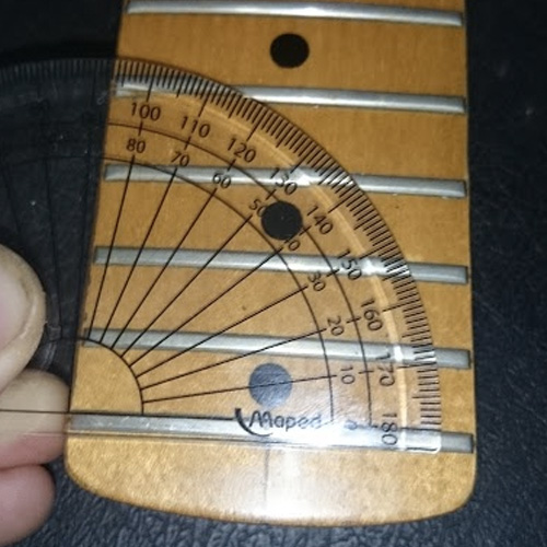
- Use a protractor to gauge the angle of neck taper. Set it on the last fret noting the angle on each side of the neck; both should match.
- Plot the angle from the baseline width points and run a line up both sides of the slot to the top.
- For a square-edged neck pocket (Tele style), mark the extended width along the baseline using the centerline as reference, check the taper angle as above and mark the routing lines.
- Now either carefully rout these lines out, or consult a professional—this must be precise. To fit a squared-off heel to a rounded contour body slot, use a scanner to print a template of your heel, and apply the above methods for trimming.
If Your Guitar Neck Is Too Narrow for the Neck Pocket
Once the centerline is established, we can deal with a too-narrow neck using shims, aka spacers, for precision fitting. Trust no shim implicitly, and always refer to centerline for every measurement. You can use any non-compressible material (credit cards, playing cards, etc.) of consistent thickness for a shim; for this demonstration, we're using 0.5mm string-lock shims, trimming one to fit the lower side slot.
- To find the shim thickness you need, measure the neck-heel width and neck-pocket width and divide the difference by two.
- Packing both sides of the slot will maintain the centerline; fixing the neck to one side will cause misalignment.
- Fix shims with the smallest drop of Cyanoacrylate possible. Even a thin film of glue can alter the slot width.
Basic Garage Wiring
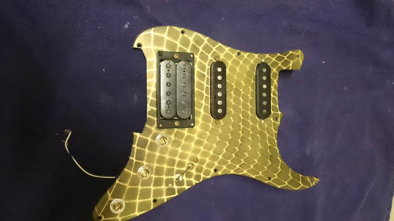
This installment addresses the wiring and fitting of all manner of elec-trickery. We’ll solder in a trio of new pickups. The bridge humbucker is a '90s-era ESP, origin unknown, while the middle is a 1986 MIJ Fender item. For the neck, we have a 1979 US Fender single coil. For an introduction to pickup selection and swapping, check out Dave Hunter’s excellent article.
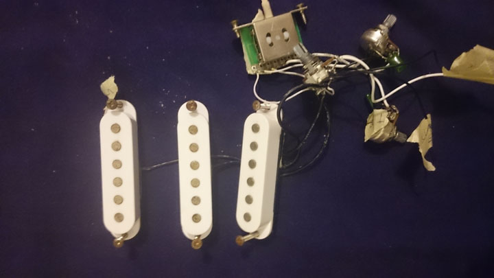
We're starting with a pillaged wiring loom from a Strat copy. Having a roadmap is helpful for the inexperienced, and a working loom may exist in another of your project guitars. No wiring to work with? Kits and diagrams are available, but the combinations are many, so start with a basic setup.
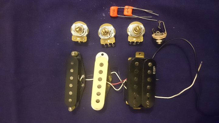
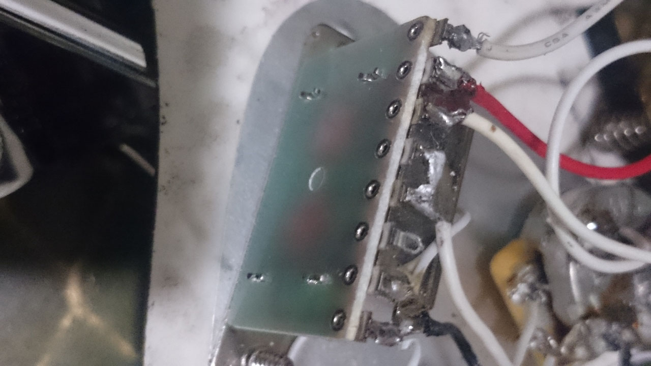
The Fender and ESP wiring matches the pickups, which we’ll incorporate into the loom. The pots are U.S. CTS units, 250K for the single coils and 500k for the ‘bucker tone dial. Fender and Gibson both use CTS—there’s no point in connecting great pickups to junk pots. The five-way switch was reliable in the donor guitar, so it’s a keeper. Always renew output jack sockets after upgrading.
Tag the donor pots, pickups and wires that lead to them before dismemberment and keep them for reference if you get confused. Use language you’ll remember and write legibly; a smear with two readable characters is not helpful on reassembly. Here’s the five step program:
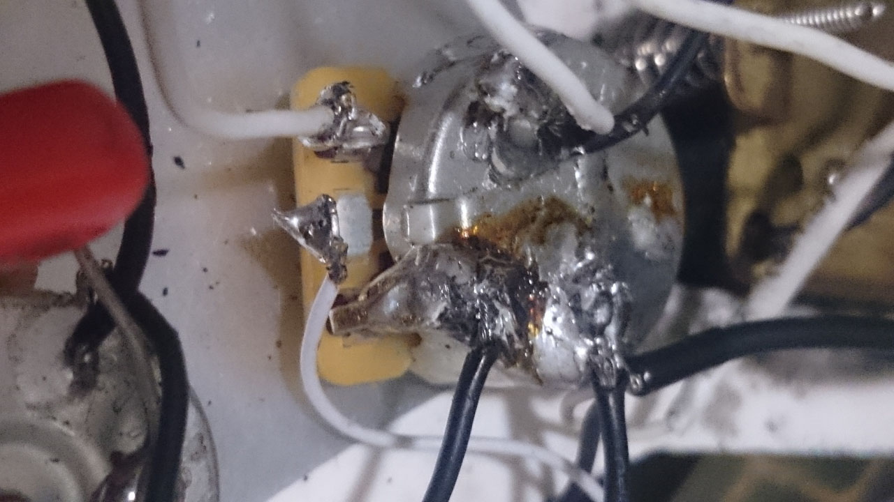
- Using a high-temp soldering iron, join all pickup ground wires and solder them to the back of the 250k volume pot. Run ground wires from here to the back of the tone pots, and add another for the spring-claw.
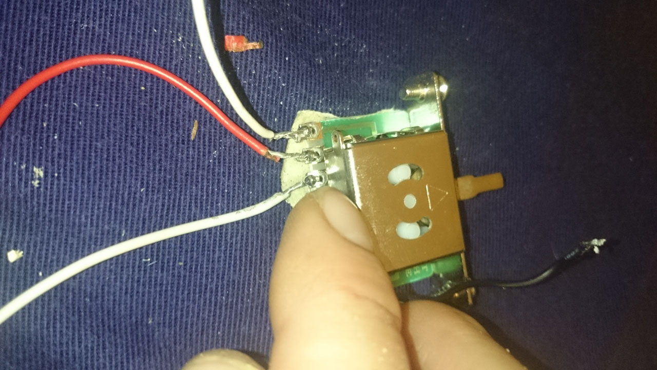
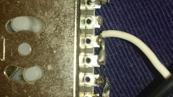
- Connect your neck pickup's positive lead to the five way switch’s 3rd position. Middle and bridge pickup positive leads connect to the 2nd and 1st positions, respectively.
- There are 3 tabs on your volume pot. Bend the 3rd position tab to contact the rear of the pot and solder it into place. Connect a hot wire to the 2nd position tab for your output socket. Bridge the number 4th and 5th position tabs on the 5-way switch and solder the hot wire from here to the 1st position tab.
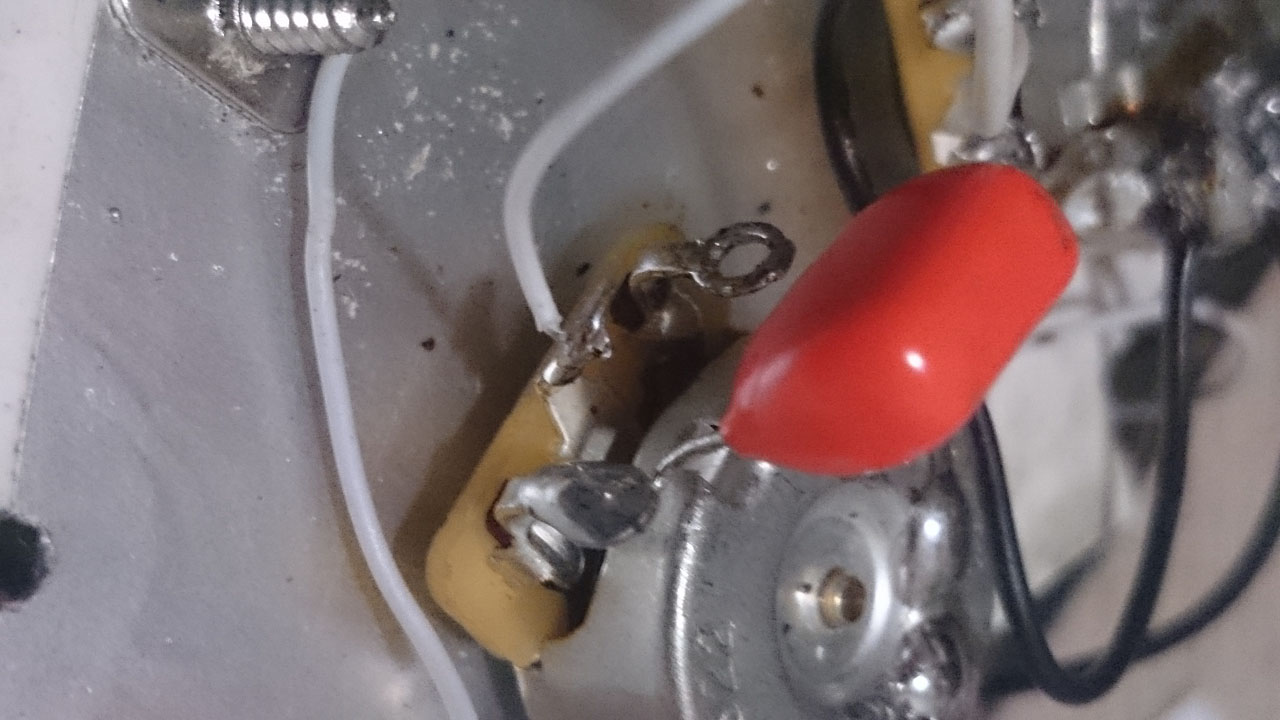
- Middle 250k tone pot needs a .022 capacitor for single coils. Solder one contact to the back of the pot and the other to 3rd position tab. The 2nd position pot tab is for the humbucker's positive lead, which gets connected to the last position tab on the five way switch. Also connect a ground from the back of this pot to the ground tab on the 5-way pickup switch.
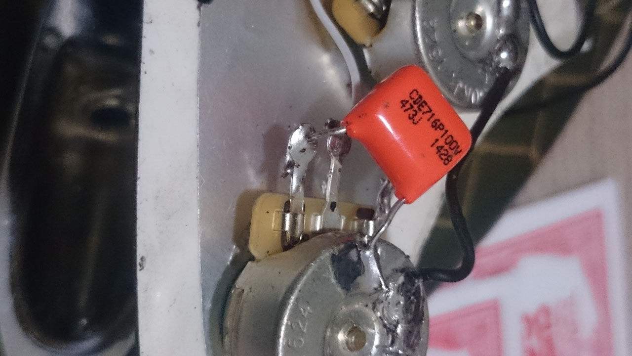
- The ESP humbucker needs a .047 capacitor soldered to the 500k rear tone pot as above. 2nd position pot tab is for the hot wire, join it to the last position on the 5-way switch. Solder in the output jack and spring-claw ground wires on assembly.

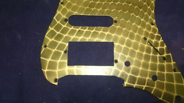
There are other wiring routes for different applications; this setup will provide standard operation. The pickguard needs trimming for a humbucker slot and Floyd Tremolo. Utility knives work if you’re on a budget and have Shawshank Redemption-style time on your hands, but a rotary tool with a grinder bit or cutting-disc is best. Starting at the tremolo:
- Remove the trem mounting posts, as they just get in the way. Insert the bridge into its cavity, using plasticine to keep it level.
- Secure the pickguard in place with a couple of screws; be aware that excess plastic will extend over the bridge.
- Using a ruler, mark the area to be removed.
- Trim away the marked area. Patience is rewarded with clean lines here.
- Fit the mounting posts and bridge to ensure free movement.

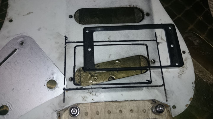
To mark out the humbucker slot, flip the pickguard so guide lines will not stain the face-side. A pickup ring is an excellent template, even if you’re not fitting one.
- Attach the pickup ring to the middle pickup mounting holes, using a ruler to run guidelines down the pickguard’s length.
- Unscrew the pickup ring and slide it down between the lines to its final position, marking the outside and inside edges – aim to fit the old slot within the borders.
- Remove the pickup ring and cut out the slot. A straight edged piece of hard waste material as a guide yields clean edges.
- For humbucker mounting holes, flip your pickup ring so the mounting holes sit flush on the pickguard. Mark the holes and drill them out. Turn your pickguard over and mount the hardware. Solder your input jack and spring-claw wires — it’s ready to screw into place.
- If you need rear humbucker routing, use your new slot to mark the area, then place the humbucker inside the marks and trace a generous margin around the mounting lugs.

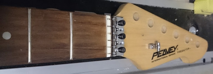
Installing a Floyd Rose Trem and Locking Nut
Here, we're installing a Floyd Rose-style floating tremolo system on a cheap, Strat-style Peavey guitar. We're using a mid‐priced licensed Floyd Rose copy, and to complete the brief, we’ll also fit a locking nut that was supplied with this tremolo. Now it’s time to operate.
It's recommended that you mount the Floyd with forward-only action, as fine‐tuning a floating trem requires luthier’s expertise. Surface mounting is possible, but because the Floyd design uses the tuning extensions behind the saddles, you'd need to make room by routing the body below the bridge.
To sink the bridge into the body you’ll need:
- A router with a 6mm bit and another 1mm smaller than your Floyd mounting studs’ diameter
- Power drill with 6mm wood boring bit and step-drill bit with graduations up to 1mm smaller than your mounting studs’ diameter
- Long ruler or straightedge
- Drafting square and protractor
- Vernier caliper
- Marking pen
- Masking tape for marking guidelines
Marking the Rout for the Tremelo
Ensure all measurements start and finish with reference to your centerline. Double check the scale length of your neck as it fits to the body, then:
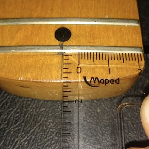
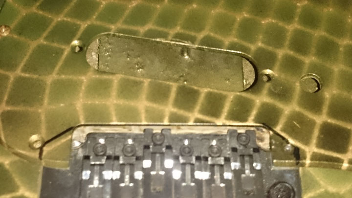
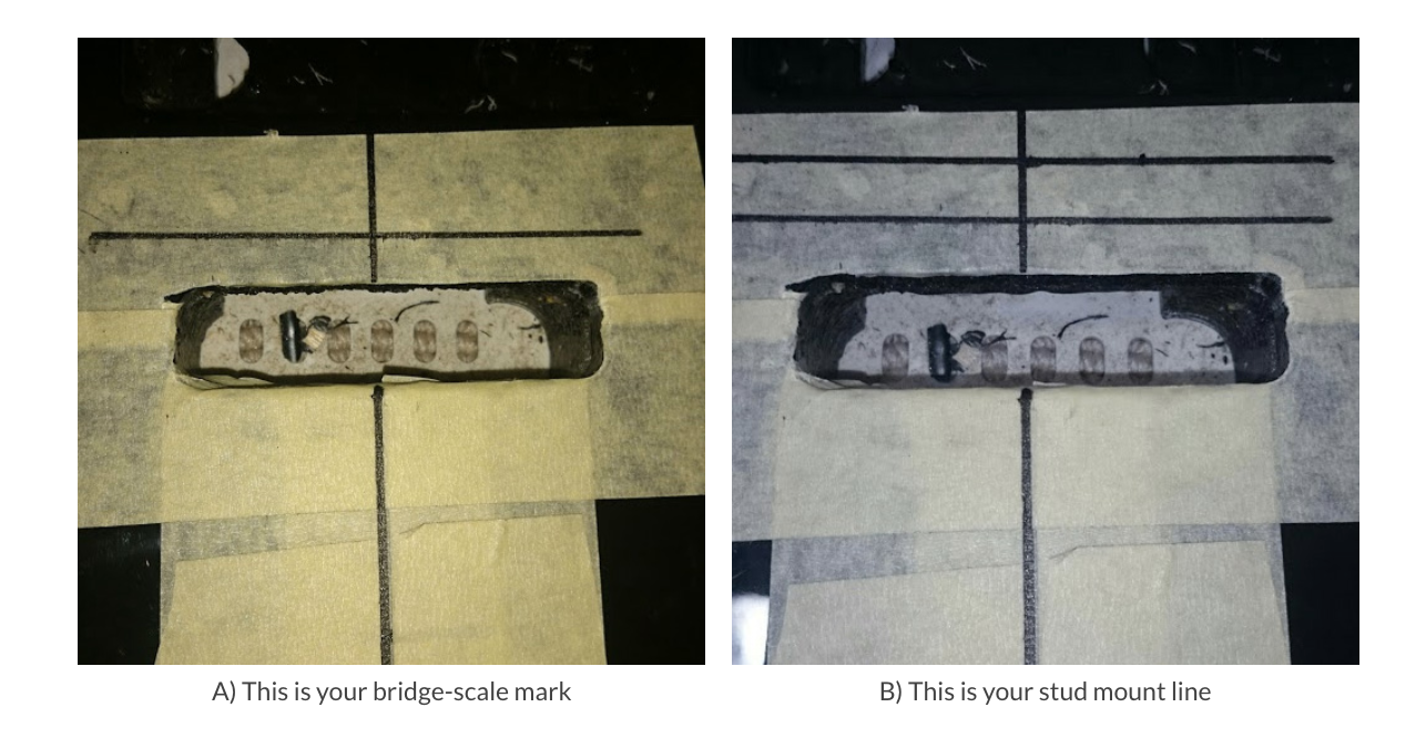
- Remove the original bridge. Plot in the exact point the scale measurement terminates on the body centerline (photo A).
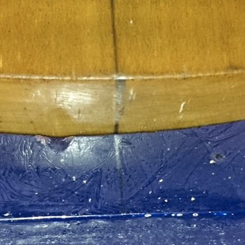
- According to Floyd Rose manufacturer's instructions, measure 10.54mm up the centerline from the bridge-scale mark and plot a 90° line out from here (photo B).
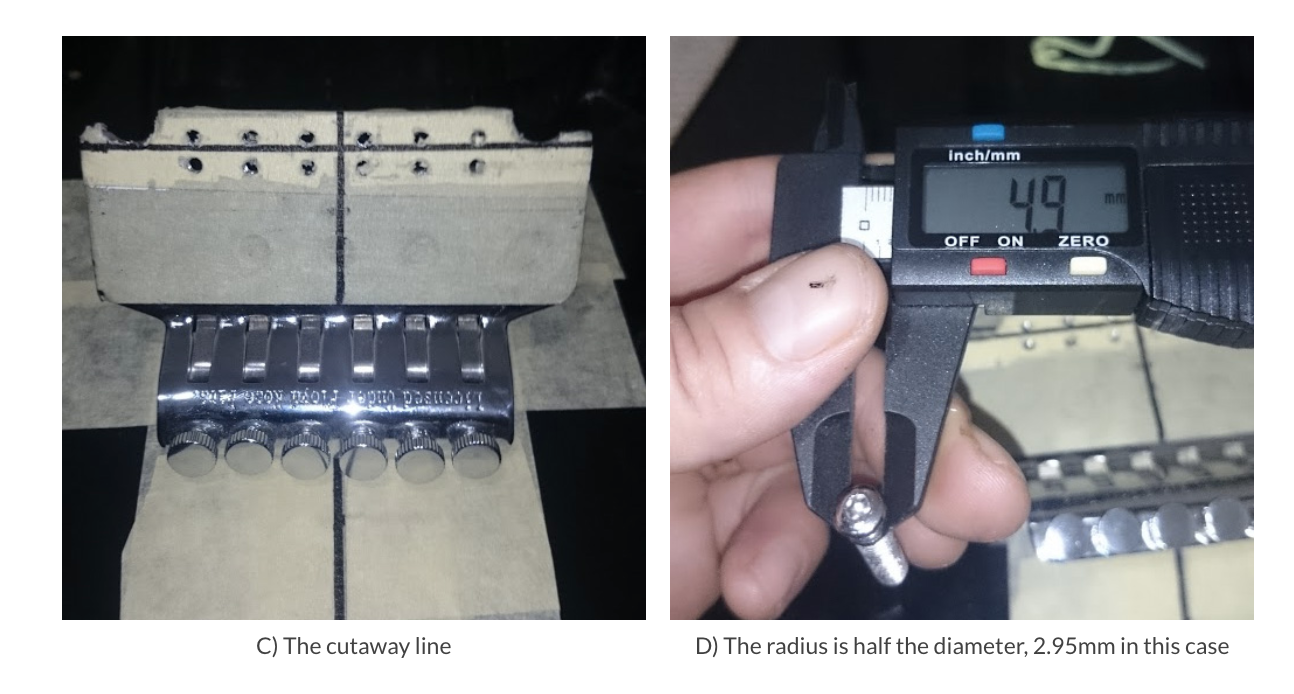
- If your trem is a copy, check that the forward saddle mount holes line up with the pivot cutaway. Add or subtract any variance from 10.54mm before you mark the line (photo C).
- Remove the saddles and mask up your base plate for marking. Draw in the centerline (photo C).
- Mark across the base plate at the lowest point of the pivot cutaways (photo C).
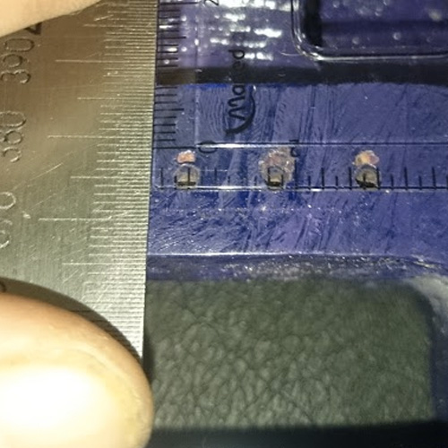
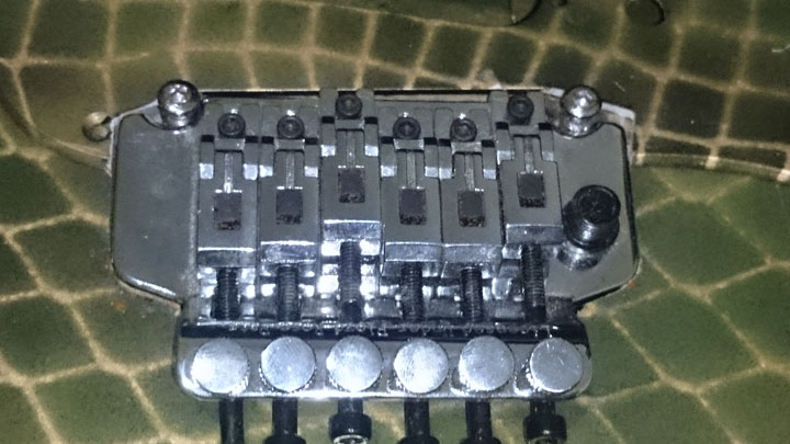
- Find the radius of your studs’ pivot point by measuring the diameter and dividing by two. Since the screw's diameter measures 4.9mm, our radius is 2.95mm. Working up from where the cutaway line crosses the centerline, mark the radius measurement on the base plate (photo D).
- Mark a 90° line from here to the edges of the bridge, this is your pivot line.
- Sit the trem on the body and line up the pivot line with the stud mount line maintaining the centerline, then secure the bridge.
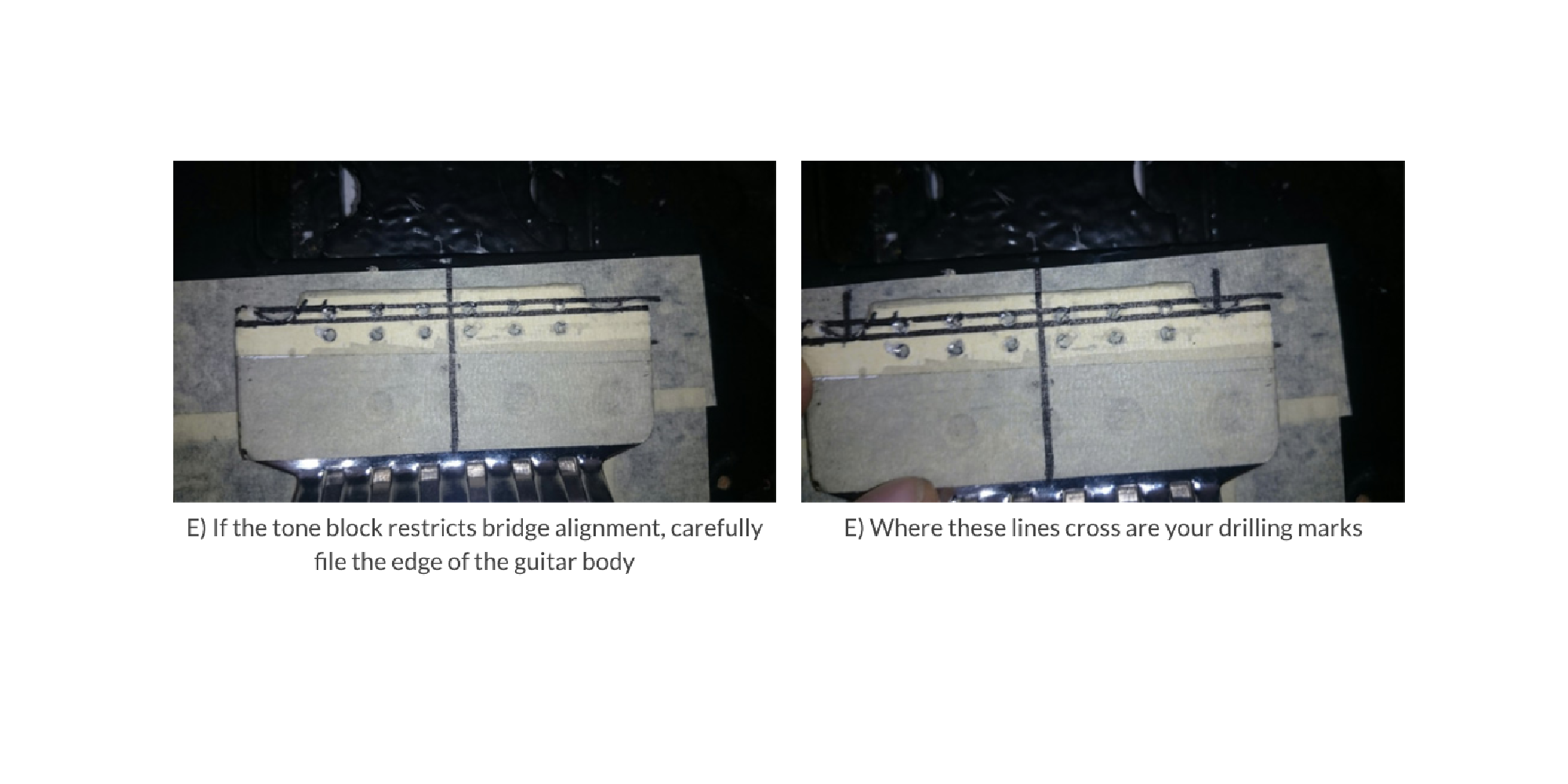
- Run a 90° line down from the stud mount line to the lowest point of the cutaways (photos E).
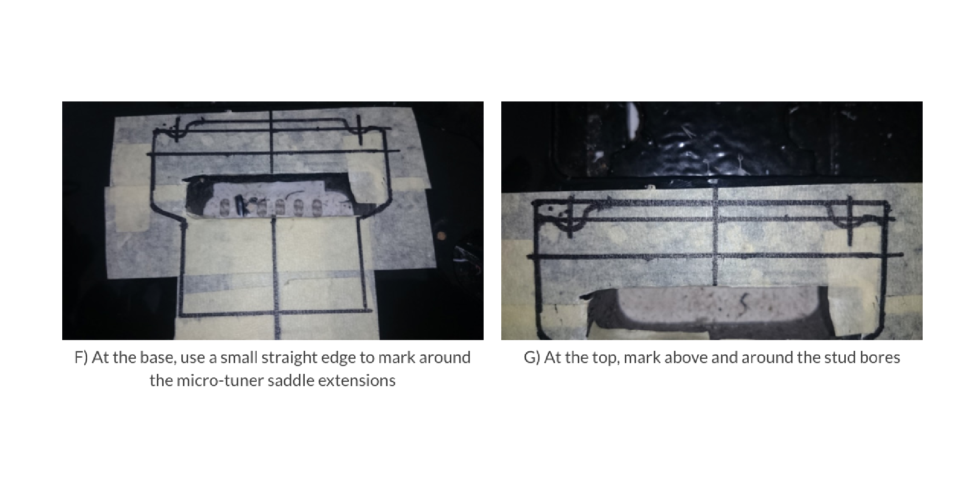
- Mark a border around the bridge plate, a small gap will ensure clean lifting action (photos F and G).
- Now remove the trem and secure body for surgery.
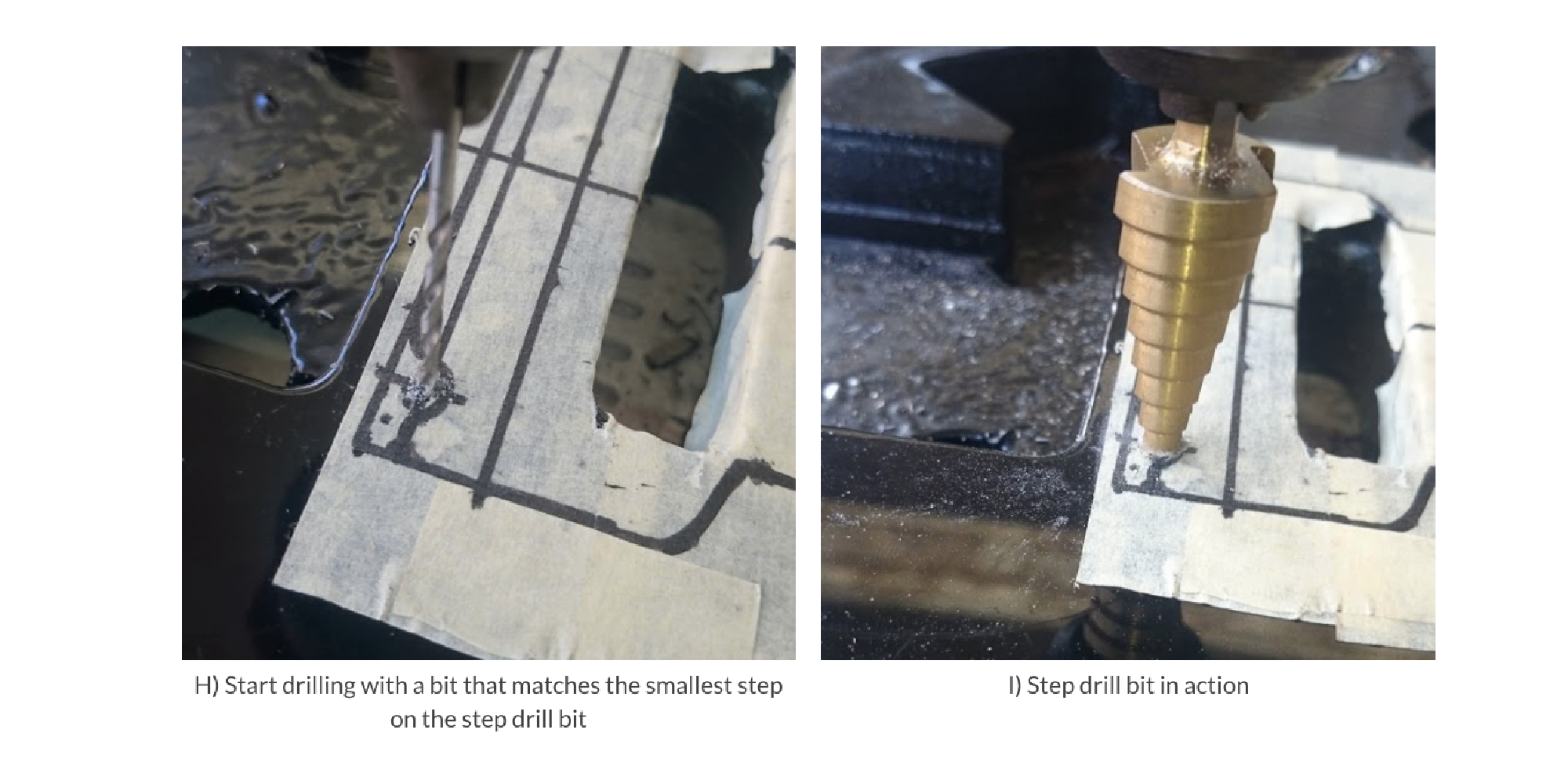
- Bore pilot holes into the mounting stud drilling marks. Use the step-drill bit to gradually widen the bores (photos H and I).
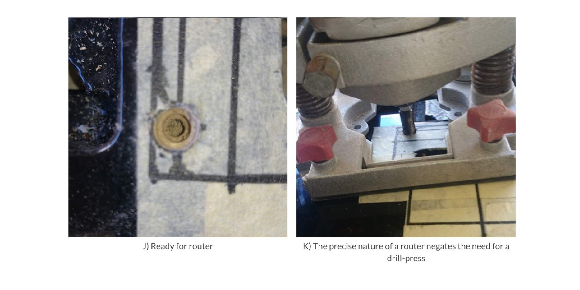
- At the step 1mm less than mounting stud diameter, don’t sink the hole, just score the surface for the larger router bit (photo J).
- Carefully drop the router bit into one of the scored holes. When correctly positioned, sink the router to match the length of mounting-studs plus 3.5mm. Repeat for the other side, now move on to routing the rest. (photo K)
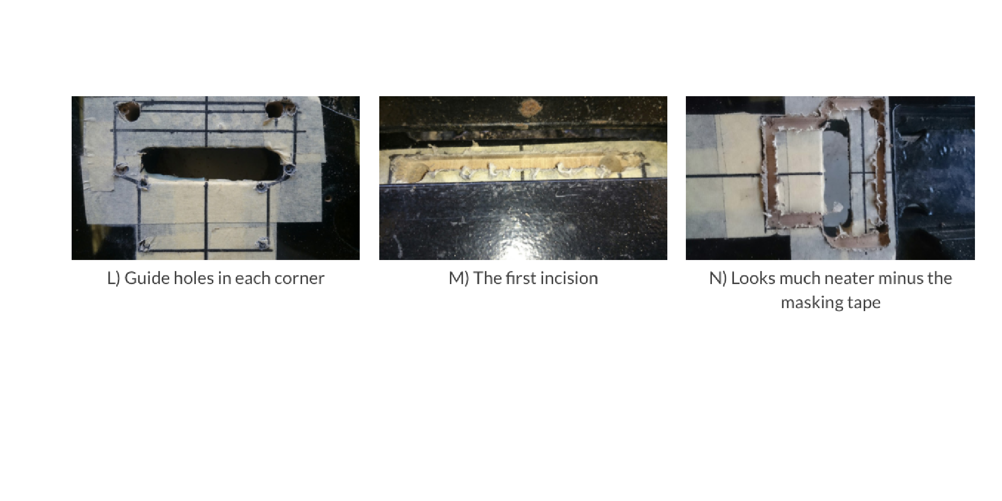
- Use a 6mm drill bit to bore guide holes inside each corner of the marked area (photo L). Place your 6mm router bit locked at 3.5mm into the top left guide hole. Use a jig or straight-edged guide rail to ensure router only travels across the body to join the top right hole (photo M). Complete the perimeter routing using this method between all guide holes (photo N).
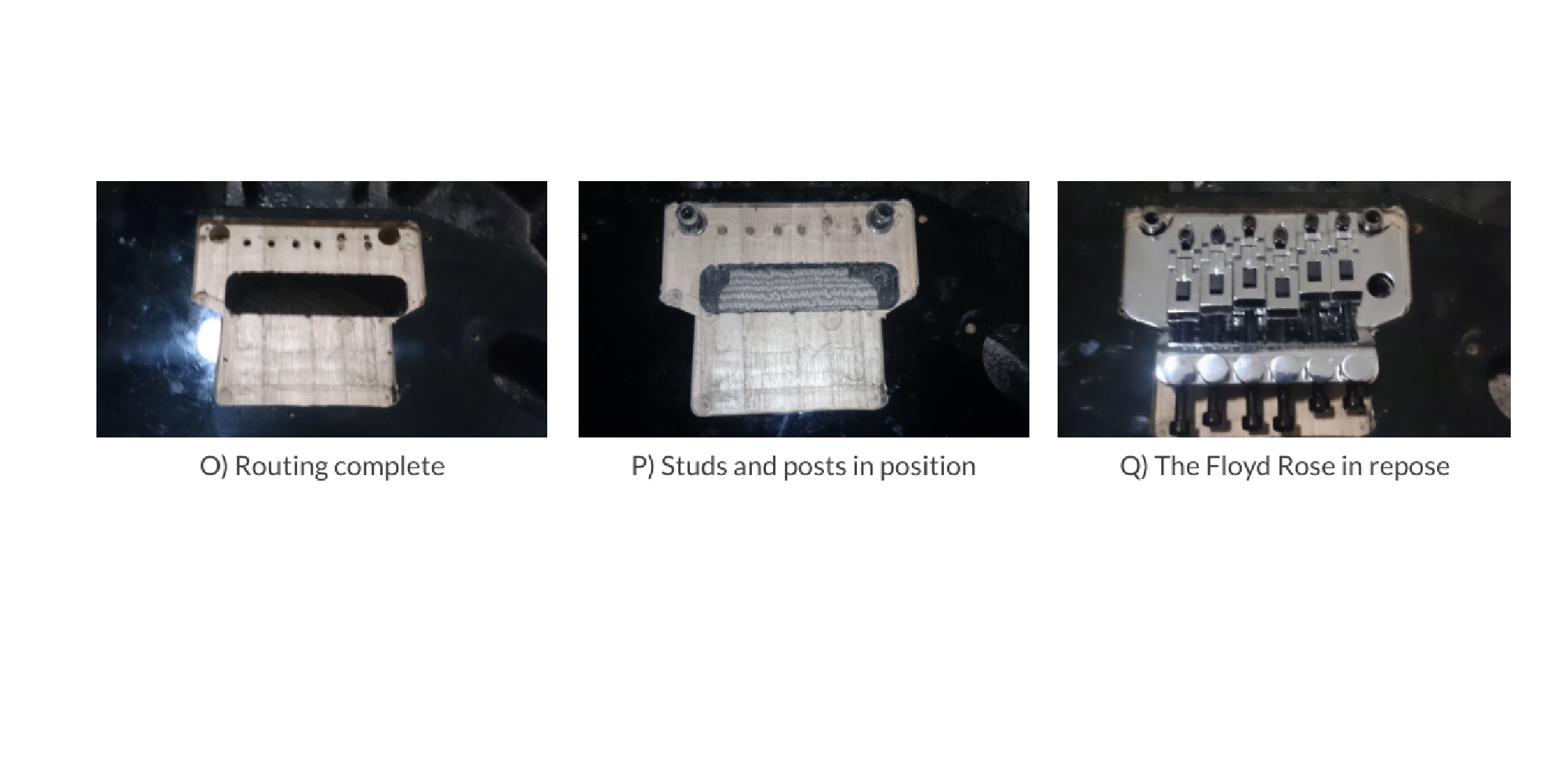
- The routing can now be completed without risking the straight edges (photo O). You’re done - tap the post-studs into their bores, screw the posts into place and slot in the tremolo (photo P). Use your current trem claw and reinstall the springs.
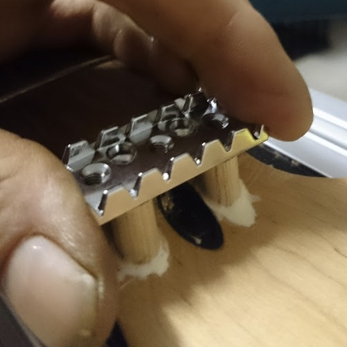
Installing the Locking Nut
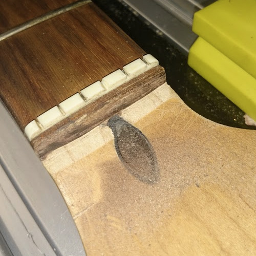
When mounting a locking nut, a pre-fitted neck would be best, but the Peavey neck will need to be modified to accept the hardware, using the original nut as a zero fret to preserve string alignment. There’s not enough "meat" above the nut to securely mount the locking nut, so here’s the least destructive fix:
- Mark across the fretboard 2mm above the nut, measure your locking-nut depth, you’ll want a slight transition of about 1-2mm to drop the strings into the lock from the original nut.
- Secure your neck and rout the end of the fretboard to the required depth. Beware! Some necks have a metal plate below the nut over the truss rod; do not rout this, a luthier will need to mill it. (photos R, S, and T)
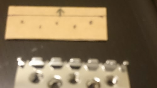
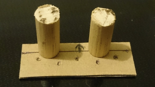
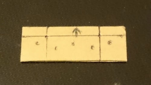
- Make a base template of your new nut. Find two 9mm diameter hardwood dowel pins; mine is Tasmanian Oak, but any hardwood will do. Measure 4.5mm down from the top of your template and mark a line across (photo U).
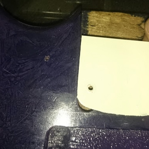
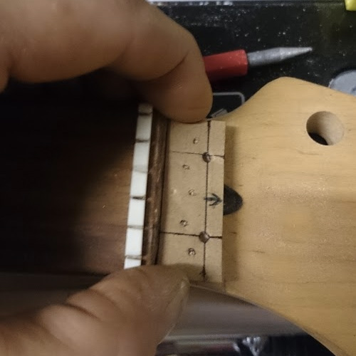
- Mark all holes in your locking nut onto your template (photo U). Find two spots on both sides of the truss-rod slot where the pins will not block any holes, top edge of the pins flush with the top edge of the locking nut (photo V). Mark your template from the top edge of the dowels down to the neck. Where these lines and the 4.5mm line across meet are your drill points (photo W).
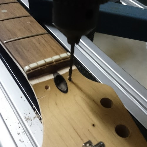
- Place your template hard up to the routed fretboard edge (photo X). Drill down into the neck using several bits to work up to 9mm, deep enough that your pins sit securely (photo Y). Fit your pins and level them off (photo Z). Check that your locknut is level on the routed area and the two extension pins, then use strong adhesive to secure the dowels permanently (photo AA). Mount your locking-nut (photo BB)
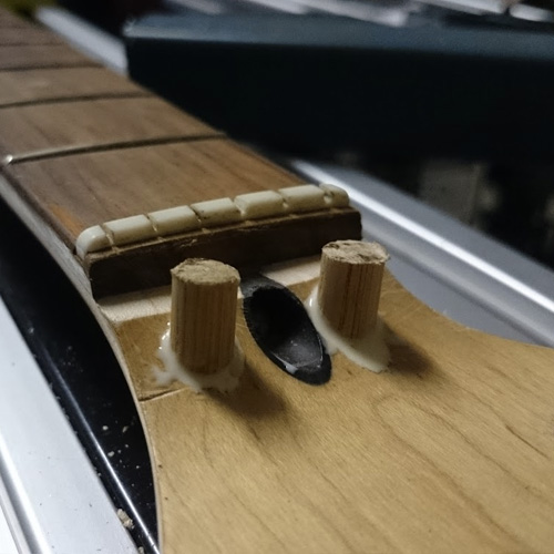
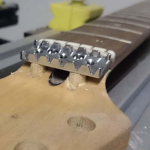
Not only will the locking nut sit securely in place instead of floating ahead of the fretboard, but truss-rod adjustment is unimpeded, and we’re done for now from block to lock.
Guitar Paint and DIY Custom Finishes
Here, we'll look at what it takes to paint or refinish your guitar, along with three custom finish templates.
Prepping The Body
Completely stripping a guitar body is more difficult than many realize. Even cheap guitars usually have durable finishes that require effort to remove. The inside curves of a Stratocaster’s horns are particularly frustrating without the right power tools. Here are some hard and fast tips:
- To paint over an existing finish, first fill any chips with auto body filler. Then lightly sand the whole surface to an even, dull finish with 800 grit sandpaper. This will give the new paint something to grab. Glossy surfaces won’t hold a top coat and will chip or scratch easily.
- Let any fillers dry for 24 hours. Hardening chemicals produce gas as the product cures, which causes bubbles if you immediately paint over them. Be patient.
- Rub the body down with turpentine to remove grease, fingerprints, and other foreign substances. Be thorough and let it dry completely before painting.
- Don’t use undercoat. Modern acrylic primer spray paint is almost exactly the same formula as topcoats. Finishing paints have evolved past needing an undercoat to grip the surface. Just prep well and spray your chosen color.
- Use a drop sheet and maybe erect a small spray tent to avoid dust and day-glo green overspray covering everything around. Paint doesn’t disappear into the air. It settles wherever the drafts in your workspace take it. Ensure your “booth” has adequate ventilation. Otherwise you risk dangerous propellant inhalation. Five by five feet is adequate. Purchase cheap clean sheets from the thrift shop for marital harmony.
- To move the body around to paint corners, inside edges and the underside, bolt a scrap neck or suitably sized piece of timber to the body and clamp it to something solid. This also masks the neck-pocket surfaces. Avoid spraying there. Even a thin coat can skew neck alignment.
Guitar Finish Ideas
To get those creative juices flowing, I’ve shared three templates below that you can take and run with. They may not be your cup of tea, but let these examples open your mind to all the other possibilities out there.
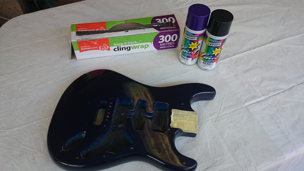
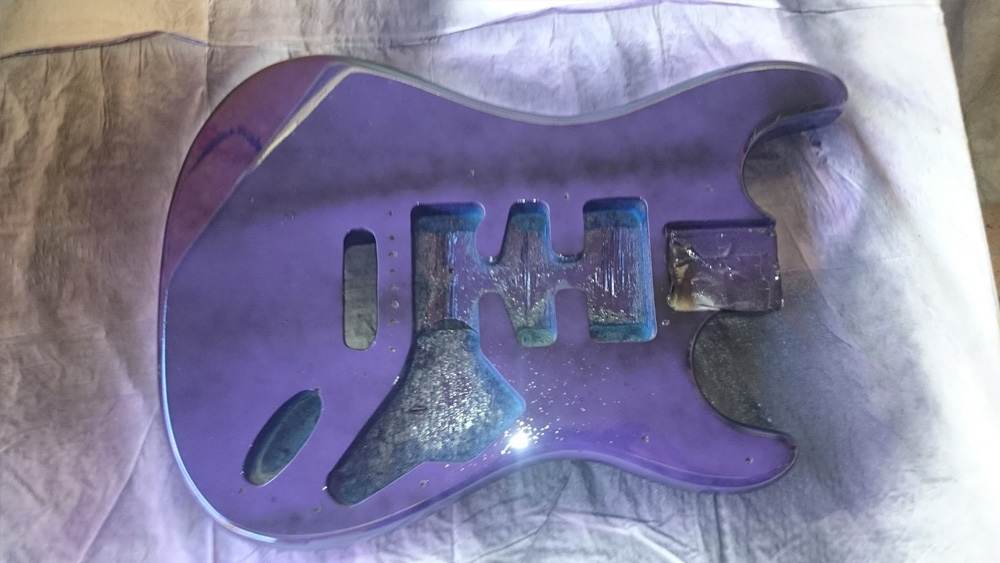
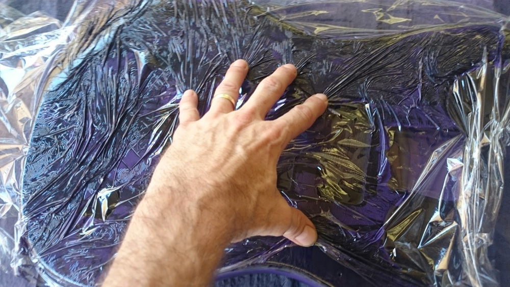
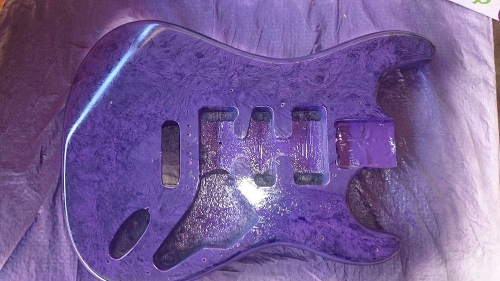
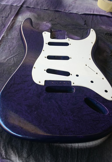
Marbling Effect
This cool effect simply requires plastic food wrap and two colors. This is a fast, simple method to produce a stunning finish.
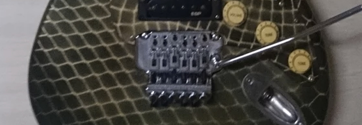
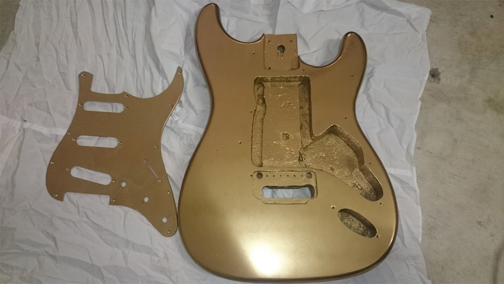
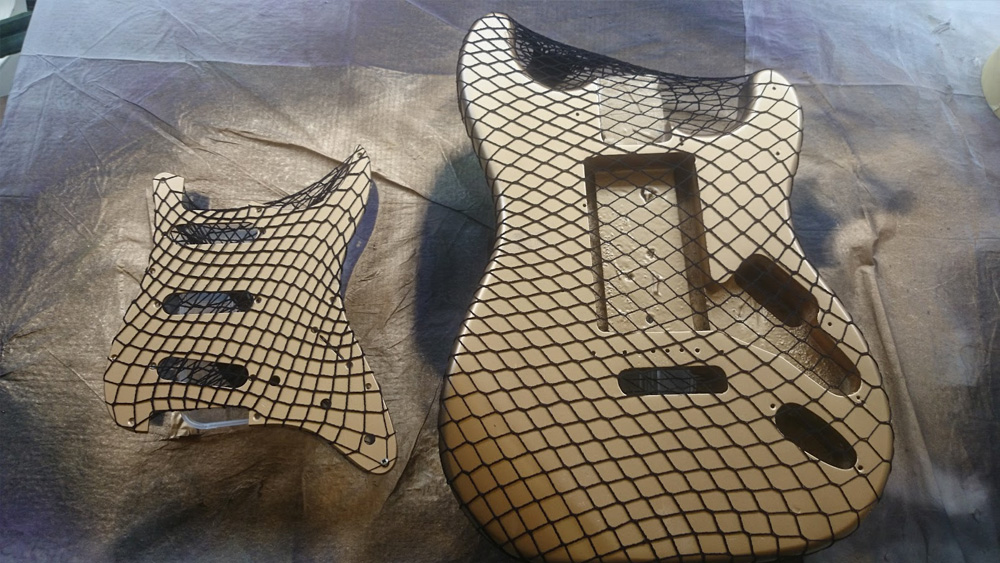
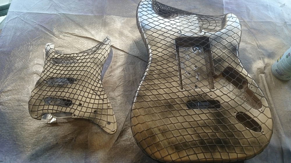
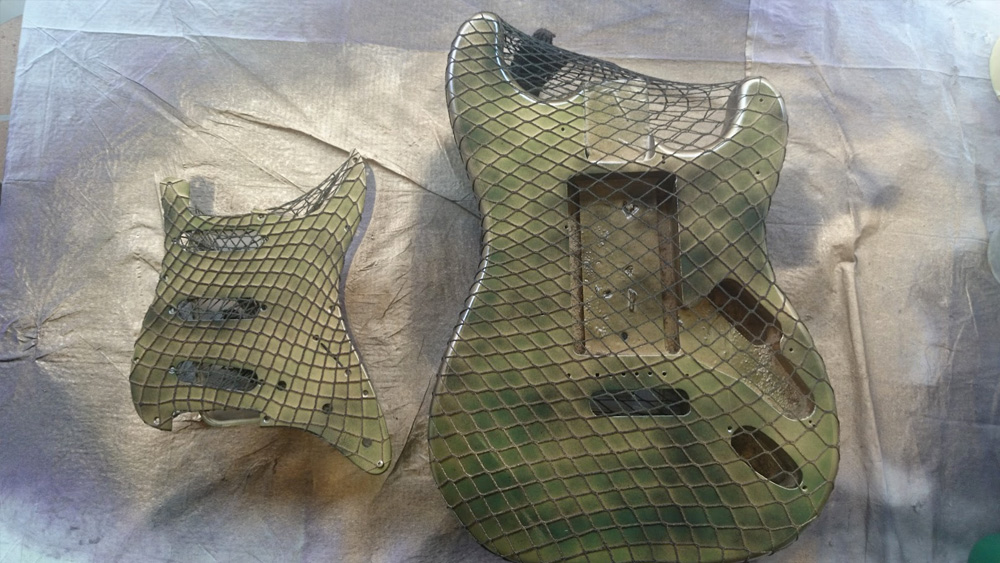
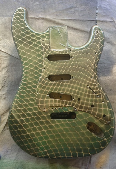
Reptilian Scales
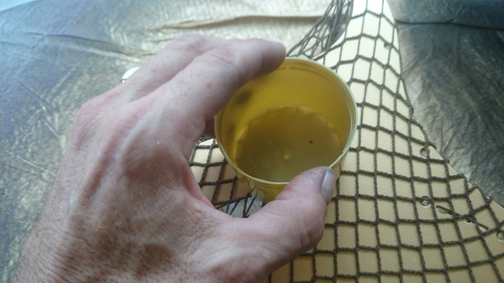
You can produce this effect with a dark or metallic base coat, a fishnet stocking and some biological topcoat colors. Choose colors to match your favorite lizard/snake/dragon.
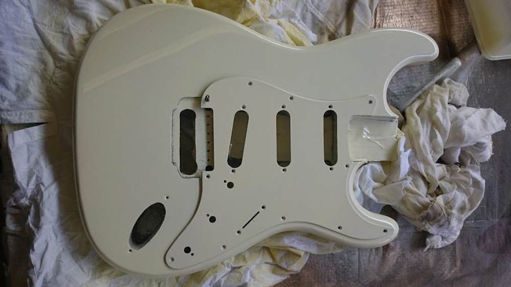
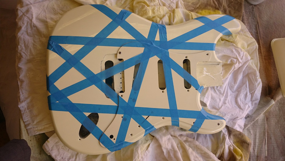
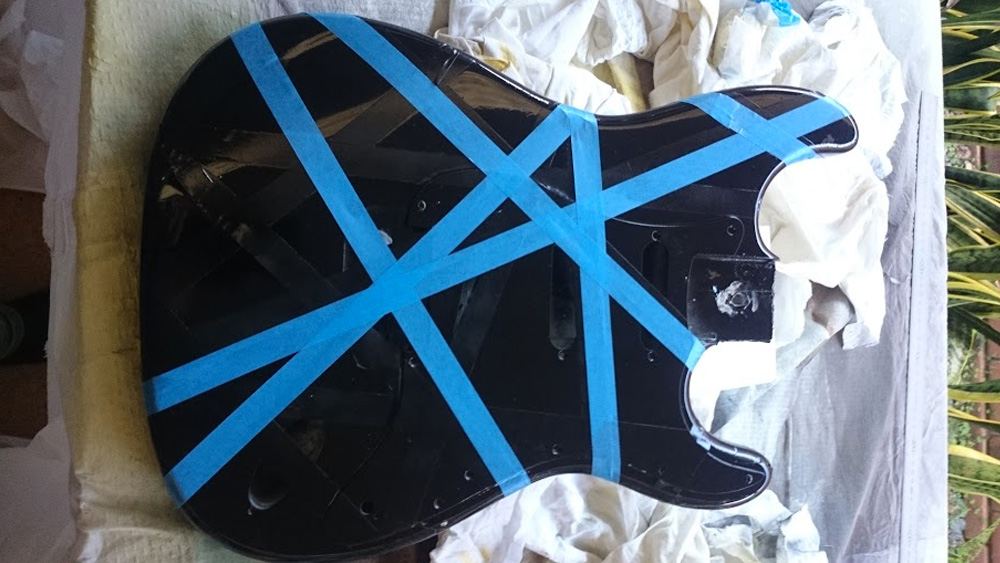
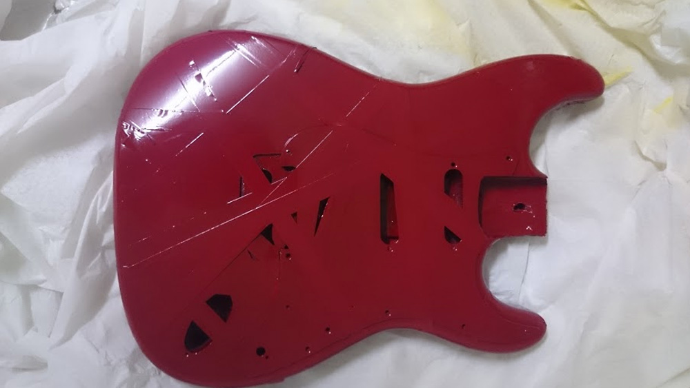
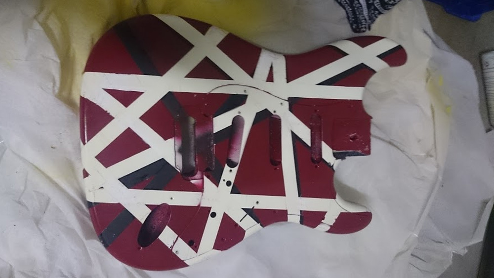
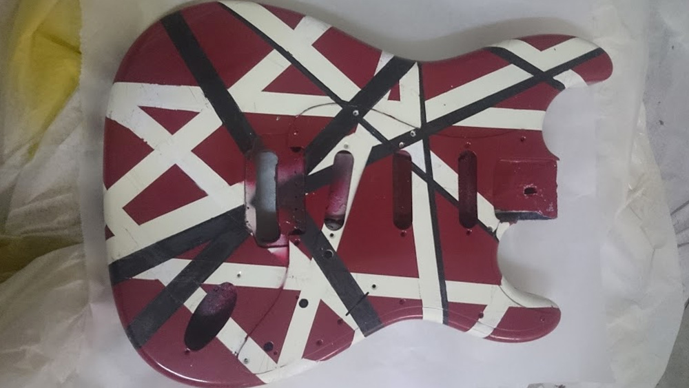
Classic Frankenstein Striping
Finally, the classic tape and layer method. I’ve always wanted to give this a go. You can create your own pattern as an homage to Edward’s original, but for perfect replication, find an image on the web and use it as a guide for stripe placement.
It’s worth mentioning that this pattern is actually protected intellectual property of the EVH brand. That means creating this guitar is just for you and you alone. If you try to sell it on Reverb (or anywhere), it creates a very unfun series of messages from EVH lawyers to Reverb staff and then to you. Don’t do it.