![DOEPFER A-190-8 USB - MIDI TO SYNC INTERFACE : BRAND NEW : [DETROIT MODULAR] image 1](https://rvb-img.reverb.com/i/s--wxMZG3df--/quality=medium-low,height=800,width=800,fit=contain/h02ytqffco60qldi8lrl.jpg)
DOEPFER A-190-8 USB - MIDI TO SYNC INTERFACE : BRAND NEW : [DETROIT MODULAR]
This seller has not set a shipping cost for Estonia. Please contact them to ask about shipping.
Original Price€164.33
11% price drop
New Price€179.32
Incl. VAT
+ Shipping
Only 1 left
Grab it before it's gone
Listed:over a month ago
Views:117
Saves:9

Royal Oak, MI, United States
30-Day Return Policy
Enjoy peace of mind with your new gear
Our users rate Reverb
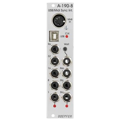
Module A-190-8 is a Midi/USB to Sync interface. The main application of the module is the control of clocked A-100 modules like sequencers (), sequencer controllers (), trigger divider ( or ), trigger sequencer () and similar units. It may be used also to reset or sync LFOs (e.g. , , ) or to trigger envelope generators (, , , ) with a fixed clock rate.
These are the most important features of this version of the module:
- Midi input (recognizes only Midi realtime messages clock, start, stop and continue)
- USB input for Midi via USB
-
Clock outputs:
- 96: outputs the Midi clock 1:1 (96 pulses per measure/ppm or 24 pulses per quarter note/ppq)
- 32: outputs the Midi clock divided by 3 (32 pulses per measure/ppm or 8 pulses per quarter note/ppq)
- 16: outputs the Midi clock divided by 6 (16 pulses per measure/ppm or 4 pulses per quarter note/ppq)
- 8: outputs the Midi clock divided by 12 (8 pulses per measure/ppm or 2 pulses per quarter note/ppq)
- 1: outputs a pulse at the start of each measure
-
Other outputs:
- Start: outputs a pulse at each Midi Start or Continue message or generates a gate signal that remains in the high state until a Midi Stop message occurs (selectable via jumper)
- Stop: outputs a pulse at each Midi Stop message
- Reset: outputs a pulse at each Midi Start message that follows a Midi Stop message
- Wait control input, can be selected by means of a jumper between Gate function or Switch function: in Gate mode the positive edge of a gate signal is used to init the Wait state, in Switch mode an external switch that connects to GND is used to init the Wait state (equivalent to Switch-Trigger)
- Wait button / Wait control input: Whenever the Wait button is operated or a positive voltage is applied to the Wait input the module waits for the next measure start until the clock signals are generated.
- LED displays for clock, "1" and start (display of Start depends upon the chosen Start mode, see above)
- output voltages can be selected between +5V and +12V by means of an internal jumper (for DIN Sync applications +5V has to be used !)
- firmware updates via USB (provided that there will be updates available)
Technical remarks:
- In case that the inverted version of a signal is required the trigger modifier may be used.
-
An internal jumper is used to define if the Start output generates only a short pulse as soon as a Midi start message is received or if it remains in the high state until a Midi stop signal is received.
- To control the sequencer modules or both versions will work because only the rising edge of the start signal is used.
- To control DIN SYNC equipment the "long" version of the start signal has to be chosen (i.e. the signal remains high until a stop is recognized) and the output voltage has to be set to +5V ! The +12V setting may destroy units equipped with Sync DIN sockets ! For this application a special cable with two 3.5 mm jack plugs on one side and a DIN5 male connector on the other side has to be made. For details concerning the DIN Sync specification please refer to our .
- The meaning of the jumpers is described in this document:
Tiefe/Depth: 50 mm (gemessen an Rückseite der Frontplatte / measured from the rear side of the front panel)
Strombedarf/Current: 50 mA
| Condition | Brand New (New) Brand New items are sold by an authorized dealer or original builder and include all original packaging.Learn more |
|---|---|
| Brand | |
| Model |
|
| Categories | |
| MIDI I/O |
|
| Synth Module Function |
|
| Horizontal Pitch |
|
| Modular Synth Format |
|
Product safety information may be available here.