Doepfer A-165-2 Digital Modifiers
Price€128.43
Incl. VAT
+ €63.03 Shipping
Only 1 left
Grab it before it's gone
Listed:over a month ago
Views:72
Watchers:1

Burbank, CA, United States
30-Day Return Policy
Enjoy peace of mind with your new gear
Our users rate Reverb
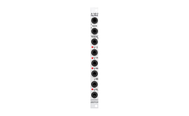
Module A-165-2 includes six modification circuits for digital signals (clock, gate, trigger, start, stop etc.) which are derived from the two input signals Input 1 und 2:
- inverted signal of Input 1 (labelled 1)
- inverted signal of Input 2 (labelled 2)
- T flipflop (toggle flipflop), controlled by Input 1, this output changes it's state whenever a the rising edge of Input 1 appears (labelled 1/2, as it works similar to a 1:2 frequency divider)
- Set/Reset flipflop, this output changes it's state to "high" during the rising edge of Input 1 and turns "low" during the rising edge of Input 2 (labelled RS)
- inverted output of the Set/Reset flipflop (labelled RS)
- pulse output, during both the rising and falling edge of Input 1 a short trigger pulse with about 50 ms lenght is generated (labelled with the sign ± and a rectangle pulse symbol)
The outputs 2, 1/2, RS and the pulse output are equipped with LEDs that display the state of the output in question. The output level for all six outputs can be set to 0/+5V or 0/+11V by means of a jumper on the pc board.
Voltage thresholds for the input voltages: voltages below +0,8 V are treated as "low", voltages above +3 V are treated as "high"
| Condition | Brand New (New) Brand New items are sold by an authorized dealer or original builder and include all original packaging.Learn more |
|---|---|
| Brand | |
| Model |
|
| Categories | |
| Horizontal Pitch |
|
| Modular Synth Format |
|
| Synth Module Function |
|
Product safety information may be available here.