
Doepfer A-174-4 3D Joystick
Only 1 left
Grab it before it's gone

30-Day Return Policy
Enjoy peace of mind with your new gear
Our users rate Reverb
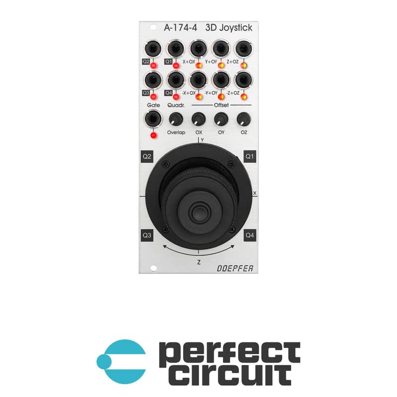
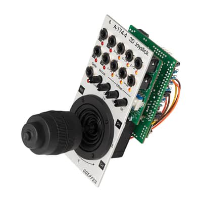
The Doepfer Module A-174-4 modules outputs three control voltages generated by a spring-loaded X/Y cross potentiometer (so-called joy stick) and a Gate signal. The control voltages for X and Y are controlled by the X and Y position of the joystick in the usual way. The third control voltage Z is controlled by the rotation of the spring-loaded joystick knob. The Gate signal is generated by a button at the center/top of the joystick knob.
For each control voltage the non-inverted signal (X, Y, Z) as well as the inverted signal with adjustable offset (-X+XO, -Y+YO, -Z+ZO) are available. The generic joystick control voltages are bipolar, i.e. they range from typ. -5V (lowest position) via 0V (center position) to typ. +5V (highest position). The "Overlap" switches can be used to add a fixed offset voltage of typ. +5V to the non-inverting output in question so that the output voltage range changes to typ. 0...+10V (rather than -5...+5V). That's necessary if e.g. a VCA has to be controlled, which requires a pure positive control voltage range. The switches are named "overlap" because they allow the overlapping of the non-inverting CV output (X, Y, Z) with the inverting output (-X+XO, -Y+YO, -Z+ZO) for crossfading applications. With the overlap switch "on" and appropriate setting of the offset control it's possible to obtain a control voltage range of 0...+10V for the non-inverting output and +10V...0V (i.e. same range but opposite direction) for the inverting output.
| Condition | Brand New (New) Brand New items are sold by an authorized dealer or original builder and include all original packaging.Learn more |
|---|---|
| Brand | |
| Model |
|
| Categories | |
| Horizontal Pitch |
|
| Synth Module Function |
|
| Modular Synth Format |
|
Product safety information may be available here.