Doepfer A-174-4 3D Joystick
Original Price$202.65
New Price$159.60
$43.05 price drop
+ $66.81 Shipping
$3.34 shipping when combined
Only 1 left
Grab it before it's gone
Listed:over a month ago
Views:906
Watchers:25
Offers:0

Paris, France
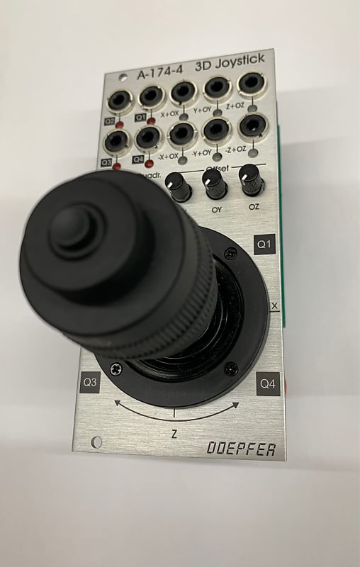
Module A-174-4 generates several control voltages and a gate signal controlled by a spring-loaded X/Y cross potentiometer (so-called joy stick). The control voltages for X and Y are controlled by the X and Y position of the joystick in the usual way. The third control voltage Z is controlled by the rotation of the spring-loaded joystick knob. The gate signal is generated by a button at the center/top of the joystick knob. As an additional feature four control voltages are generated that are assigned to the quadrants of the Cartesian coordinate system. These quadrant voltages are derived from the X and Y voltages by means of a special algorithm.
For each joystick function the non-inverted signal (X, Y, Z) as well as the inverted signal (-X, -Y, -Z) is available. The generic joystick control voltages are bipolar and range from typ. -5V (lowest position) via 0V (center position) to typ. +5V (highest position). By means of the Offset controls OX, OY and OZ a variable voltage of up to 5V can be added to the generic voltages. That way it's possible that the X, Y and Z outputs become pure positive (0...+10V instead of -5V...+5V). That's necessary if e.g. VCAs have to be controlled, because VCAs require a pure positive control voltage. The offset voltages can be adjusted by means of three small potentiometers. When the control in question is fully CCW no offset is added and the "pure" control voltages X, -X, Y, -Y, Z and -Z without offset are generated. As soon as the offset control in question is moved clockwise up to +5V are added to the voltage in question. The offset voltages are also added to the inverting outputs. With max. offset the range of an inverted output becomes also pure positive (+10V...0V instead of +5V...-5V). These six voltages are output at the sockets "X+OX", "-X+OX", "Y+OY", "-Y+OY", "Z+OZ" and "-Z+OZ". Each of these outputs is equipped with a dual color LED (red/yellow) that displays the present voltage and allows to distinguish between positive (red) and negative (yellow) voltages.
On top of this the four quadrant voltages Q1, Q2, Q3 and Q4 are calculated. A quadrant voltage becomes positive when the joystick is positioned in the quadrant in question. The absolute value of the voltage depends upon the position of the joystick lever in the quadrant. By means of the Overlap control overlapping of the voltages between the quadrants is attainable. When the overlap control is fully CCW there is no overlapping, i.e. only the control voltage of the currently addressed quadrant becomes positive, all others are zero. As overlap is increased the voltages overlap more and more. E.g. both outputs Q1 and Q2 become positive in the 12 o'clock position of the lever when the overlap control is turned up. The overlapping increases with the position of the Overlap control. We will explain this behaviour by means of a drawing shortly. Each quadrant output is equipped with a single color LED that displays the present voltage. The quadrant outputs provide only positive voltages in the range 0...+10V.
| Condition | Brand New (New) Brand New items are sold by an authorized dealer or original builder and include all original packaging.Learn more |
| Brand | |
| Model |
|
| Categories | |
| Made In |
|