Doepfer - A-174-4 3D Joystick
Price$239
+ $10 Shipping
$7.50 shipping when combined
Only 1 left
Grab it before it's gone
Listed:over a month ago
Views:835
Watchers:27

Pomona, CA, United States
Only 1 left
Grab it before it's gone
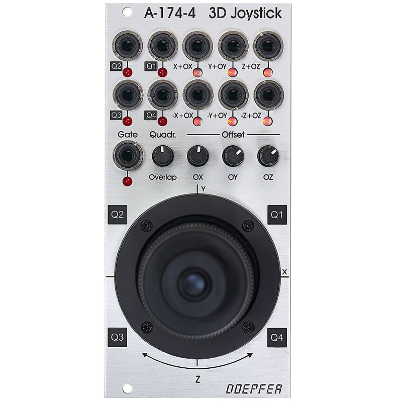
Module A-174-4 outputs three control voltages generated by a spring-loaded X/Y cross potentiometer (so-called joy stick) and a Gate signal. The control voltages for X and Y are controlled by the X and Y position of the joystick in the usual way. The third control voltage Z is controlled by the rotation of the spring-loaded joystick knob. The Gate signal is generated by a button at the center/top of the joystick knob.
For each control voltage the non-inverted signal (X, Y, Z) as well as
the inverted signal with adjustable offset (-X+XO, -Y+YO, -Z+ZO) are
available. The generic joystick control voltages are bipolar, i.e. they
range from typ. -5V (lowest position) via 0V (center position) to typ.
+5V (highest position). The "Overlap" switches can be used to add a
fixed offset voltage of typ. +5V to the non-inverting output in question
so that the output voltage range changes to typ. 0...+10V (rather than
-5...+5V). That's necessary if e.g. a VCA has to be controlled, which
requires a pure positive control voltage range. The switches are named
"overlap" because they allow the overlapping of the non-inverting CV
output (X, Y, Z) with the inverting output (-X+XO, -Y+YO, -Z+ZO) for
crossfading applications. With the overlap switch "on" and appropriate
setting of the offset control it's possible to obtain a control voltage
range of 0...+10V for the non-inverting output and +10V...0V (i.e. same
range but opposite direction) for the inverting output.
The offset
voltages which are added to the inverting outputs can be adjusted by
means of three small potentiometers. That way different kinds of control
voltage ranges are possible, e.g.
On top of this the four quadrant voltages Q1, Q2, Q3 and Q4 are available. A quadrant voltage becomes positive when the joystick is positioned in the quadrant in question.
Each CV output is equipped with an LED that displays the present voltage.
Important note:
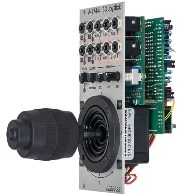
Because of the construction height of the joystick (about 7 cm) the
module cannot be installed into the cases A-100P6, A-100P9, A-100PMS6,
A-100PMS9 and A-100PMS12 during transportation as the depth of the case
cover is not sufficient. Into the base cases A-100PB and A-100PMB as
well as in all other cases without cover the module can be installed
without problems. We are about to find a solution for this problem.
| Condition | |
| Brand | |
| Model |
|
| Categories |
Module A-174-4 outputs three control voltages generated by a spring-loaded X/Y cross potentiometer (so-called joy stick) and a Gate signal. The control voltages for X and Y are controlled by the X and Y position of the joystick in the usual way. The third control voltage Z is controlled by the rotation of the spring-loaded joystick knob. The Gate signal is generated by a button at the center/top of the joystick knob.
For each control voltage the non-inverted signal (X, Y, Z) as well as
the inverted signal with adjustable offset (-X+XO, -Y+YO, -Z+ZO) are
available. The generic joystick control voltages are bipolar, i.e. they
range from typ. -5V (lowest position) via 0V (center position) to typ.
+5V (highest position). The "Overlap" switches can be used to add a
fixed offset voltage of typ. +5V to the non-inverting output in question
so that the output voltage range changes to typ. 0...+10V (rather than
-5...+5V). That's necessary if e.g. a VCA has to be controlled, which
requires a pure positive control voltage range. The switches are named
"overlap" because they allow the overlapping of the non-inverting CV
output (X, Y, Z) with the inverting output (-X+XO, -Y+YO, -Z+ZO) for
crossfading applications. With the overlap switch "on" and appropriate
setting of the offset control it's possible to obtain a control voltage
range of 0...+10V for the non-inverting output and +10V...0V (i.e. same
range but opposite direction) for the inverting output.
The offset
voltages which are added to the inverting outputs can be adjusted by
means of three small potentiometers. That way different kinds of control
voltage ranges are possible, e.g.
On top of this the four quadrant voltages Q1, Q2, Q3 and Q4 are available. A quadrant voltage becomes positive when the joystick is positioned in the quadrant in question.
Each CV output is equipped with an LED that displays the present voltage.
Important note:
Because of the construction height of the joystick (about 7 cm) the
module cannot be installed into the cases A-100P6, A-100P9, A-100PMS6,
A-100PMS9 and A-100PMS12 during transportation as the depth of the case
cover is not sufficient. Into the base cases A-100PB and A-100PMB as
well as in all other cases without cover the module can be installed
without problems. We are about to find a solution for this problem.
| Condition | |
| Brand | |
| Model |
|
| Categories |