Doepfer A-160-5 Voltage Controlled Clock Multiplier / Ratcheting Controller
Price$125
Free Shipping
Free Shipping
from Burbank, CA
Listed:over a month ago
Views:1410
Watchers:47

Burbank, CA, United States
Free Shipping
from Burbank, CA
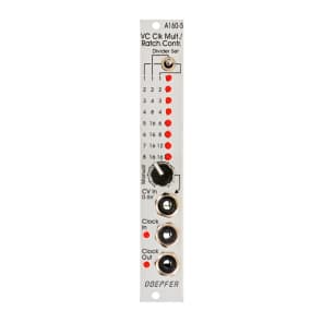
Module A-160-5 is a voltage controlled clock multiplier. The incoming clock signal (socket Clock In) is multiplied by a factor that depends upon the control voltage on socket CV In (0...+5V) and the position of the Mode switch. The multiplied clock signal is available at the socket Clock Out. According to the position of the Mode switch different clock multiplying factors are assigned to the control voltage. With 0V CV no clock output is generated. This state is indicated by "all LEDs off". With increasing CV integer factors (left position of the mode switch), power of two factors (middle position) or a mix of both (right position) are obtained. Nine LEDs are used to show the currently selected multiplying factor. In addition two LEDs are used to display the incoming and outgoing clock signal.A manual control is used to adjust the clock multiplication factor manually without the need of an external control voltage. The voltage generated by this control ("Manual") is normalled to the CV In socket. As long as no plug is inserted into the CV In socket the clock multiplication factor is adjusted by means of the manual control knob and displayed by the LEDs. For dynamic applications (like the ratcheting function described below) the manually generated CV is overwritten by the external CV which has to be fed into the CV In socket.
The module can be used for all kind of clock multiplying applications. One important example is the generation of so-called ratcheting sequences. The band Tangerine Dream is famous for these kind of sequences. A normal sequencer generates only one gate signal per step. A ratcheting sequence may have also more than one gate pulses per step. This function can be obtained by using the A-160-5: one CV output of the sequencer is used to define the number of gate pulses per step. If the control of the step in question is fully CCW the generated CV is 0V and no gate signal is generated (mute of the step). When the control of the step in question is turned clockwise one, two or more gate pulses are generated depending upon the position of the mode switch and the voltage generated by the CV at this step.
Due to the nature of clock multiplying it takes a few input clock pulses until the clock output is stable. One has to average a few input clock pulses to generate the multiplied clock output signal. Even when the input clock frequency changes it will take a few cycles until the output clock signal is correct as the module cannot forsee the future of the clock input signal. The generated clock output signal is derived from the last few cycles of the clock input signal. Consequently the module should be driven only by a clock signal with constant or slowly changing frequency.
Features
| Condition | |
| Brand | |
| Model |
|
| Categories | |
| Horizontal Pitch |
|
| Modular Synth Format |
|
| Synth Module Function |
|