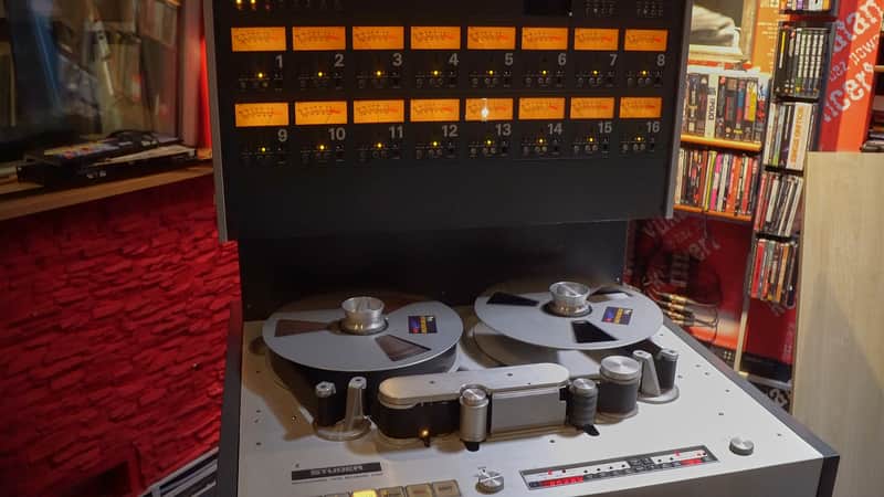
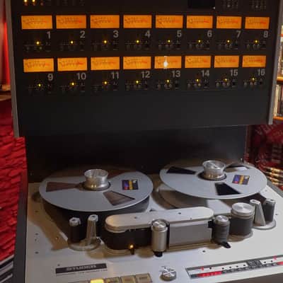
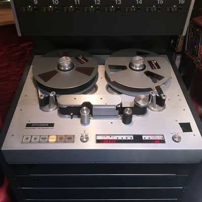
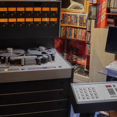
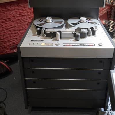
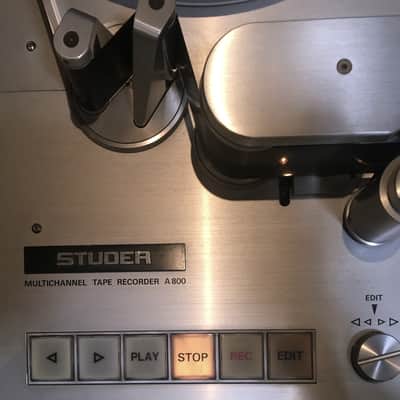

Studer A800 2" 16-Track Analog Tape Machine 1980s
This gear has sold
See similar gear from other Reverb sellers

Our users rate Reverb
Studer A800 2” 16-track multitrack tape recorder
15ips/30ips
Legendary Swiss multitrack tape recorder. Legendary quality and reliability, even now, superior to other multi-track tape recorder brands.
Low hours counter - about 4600 hours.
Crosstalk rejection and signal-to-noise ratio for this 16-track radio better than 24-track version.
Fully working condition, regularly serviced. Low heads and transport usage.
Aligned to SM911 tape. Included:
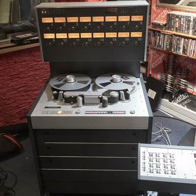
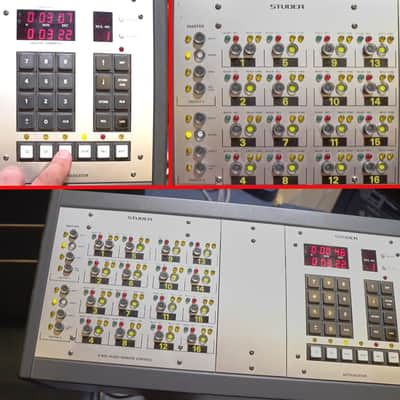
1) Audio Remote Control & Auto-Locator
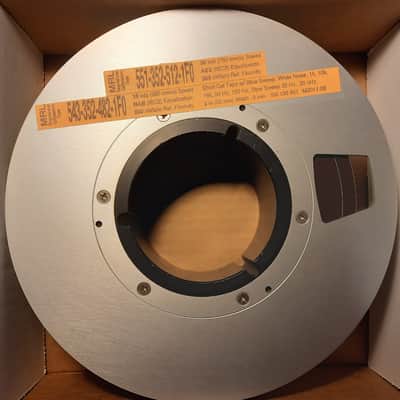
2) MRL Calibration Tape Short Cal Tape w/Slow Speed: White Noise, 1k, 10k, 16k, 50Hz, 100Hz, Slow Sweep 20Hz… 20kHz for two speeds (MRL 551-352-512-1F0*: 30 in/s speed AES(IEC2) EQ, 355 nWb/m Ref. Fluxivity, MRL 543-352-482-1F0**: 15 in/s speed AES(IEC2) EQ, 250 nWb/m Ref. Fluxivity)
* worth EUR 1362,- at Canford Audio UK currently
** worth EUR 1362,- at Canford Audio UK currently
or worth USD 555,- at the US MRL manufacturer
3) one RMG SM911* 2” tape (1524 m/5000 feet on 14” reel)*
* made in the Netherlands, worth about EUR 600,- no longer in production
4) one RMG SM911* 2" tape (762 m/2500 feet on 10.5” reel)*
* made in the Netherlands, worth about EUR 300,- PYRAL then, currently RTM branded made in France
* many RMG new (NOS, never used, perfectly stored) tapes of both sizes available on separate demand from the seller of this machine.
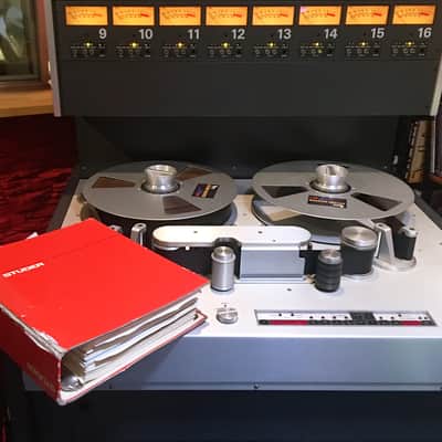
4) Service manual in pdf file form.
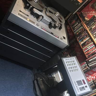
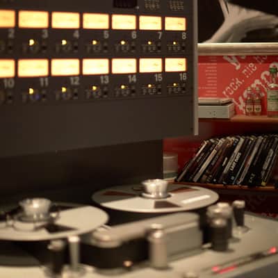
This machine in action VIDEO is linked at this listing.
Almost everyone used Studer A800 emulation plugin, but only a select few have the chance to use the original device from the real world. Transformed into a classic plugin by Universal Audio, but the 313 kg (689 lbs) of pure original Swiss precision engineering from the real world can't be matched by a string of zeros and ones.
Extremely rare is the chance to get one like this, especially in such condition.
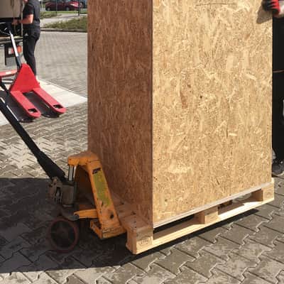
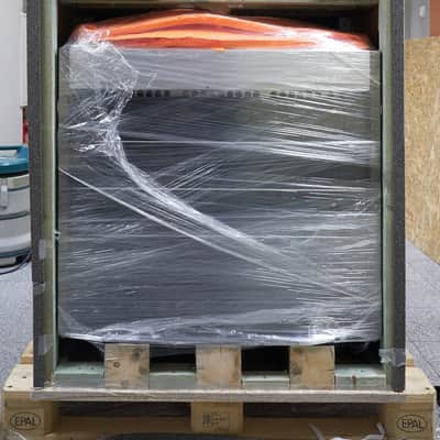
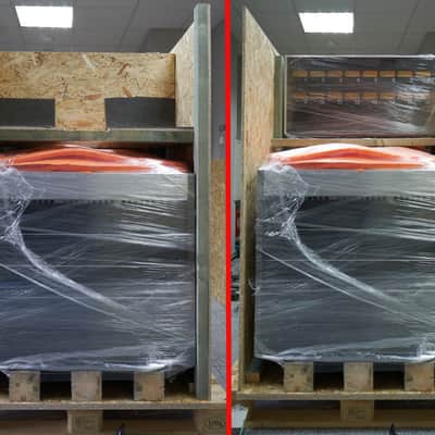
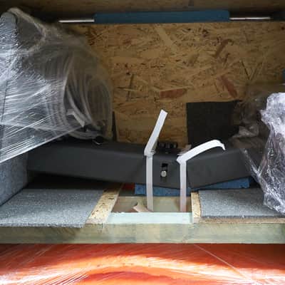
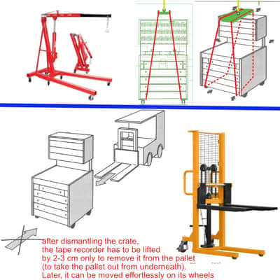
Packed safely in an OSB crate on a wood beam frame mounted on a Euro pallet. Ready for safe shipping. How to lift-up to remove from the crate - pictured on photos. Consequently, it can be moved effortlessly on its own wheels
General
In 1978 Studer introduced entirely new-designed concept of Professional Multichannel Magnetic Tape Recorder, featuring outstanding mechanical stability, 14” reel capacity, high user flexibility, ease of operation and very fast responding transport
A800 — Mechanical Stability
Extremely rugged die-cast chassis for excellent performance stability.
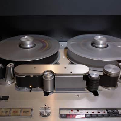
A800 — Reel Capacity
14” reel capacity (360 mm), newly designed hubs allowing quick changeover of reels.
A800 — User Flexibility
Microprocessor-controlled transport electronics. The microprocessor processes all commands received from local controls, remote controls or peripheral equipments.
A800 — Fast-responding Transport and Ease of Operation
Designed for all applications where fast and rapid action is required. Some of the features include:
- Spooling motors with very high torque, featuring high winding speed and fast reaction time. Fast line-up due to "Master Bias Setting"
- NAB/CCIR switchable by means of master switch.
- Electronic editing.
Mechanical Construction and Location of A800 Modules
Compact construction, console mounted with casters.
Rotatable transport featuring easy service.
The "brain" of the machine — the μP (1) — is located right under the transport in a card rack, which also contains all electronics (2), controlling the transport.
Electronic timer, Zero Locator, Address- Locator and Varispeed control unit (3) are located next to the large push-button assembly (4) controlling the basic transport functions.
A small, shielded box is installed below the transport, just underneath the head assembly, containing the reproduce preamplifier (5).
The main audio electronics (6) are located beneath the transport in rows of 8 channels, 2 rows of electronics for a 16-channel machine, 3 for a 24 track machine. The entire rack, containing all electronics can be tilted for easy servicing. 4 printed circuit boards of European standard format for 1 channel unit.
Clearly visible for the operator, the VU-meter panel (7) — including all operational controls for the electronics — is located above the deck.
Another control panel (8) sits on top of the VU-meter panel. It contains all master controls for the audio electronics, the operating switches and the controls for the optional code channel. All audio, transport and TLS 2000 control In- and Outputs (9) are easily accessible from the rear of the machine.
Power supplies are turned on in sequence, by means of Triacs, eliminating possible noise and spikes induced into the mains line.
STUDER A800 - Transport
The transport system of A800 is an entirely novel concept and design, featuring:
Extremely fast reaction times, enabling rapid working
DC spooling motors with very high torque, featuring fast reaction times and high winding speed.
14” (360 mm) reel capacity
Reaction time and reel capacity like a modern VTR. This concept is ideal for operation with the STUDER Tape Lock System 2000 or in any Video-Audio, Audio-Audio or Film-Audio synchronisation application.
Transport Control Featuring the Technology of Tomorrow (wording from 1978)
Greatest flexibility of the A800 concept is obtained by using a
Microprocessor (μP)
The hard-wired transport control has been eliminated and been replaced by a new flexible and "intelligent” logic. With the functional parameters defined by software only, entirely new dimensions are opening up. The control system has been designed to provide optimal access to all functional controls of transport and audio electronics, resulting in a flexibility never achieved before.
The μP is the "brain" of the control system. All transport and electronic units are controlled via several BUS systems. It generates reference voltages and frequencies, and drives all status indicators and displays as well. A special rack is containing the delay unit and the code channel electronics with the TLS 2000 interface. Here, the microprocessor controls the exact timing of erase head and record head switching. Together with the TLS 2000 a perfect electronic editing becomes possible.
Transport Control Elements
Designed in a most ergonomical way, all control elements are easily accessible.
Transport push-button assembly. Enables large buttons, easy to handle, control the basic transport functions. Status indication.
Edit control assembly. Enables easy and fast location of a point of interest on tape. Search speed adjustable.
Timer assembly with:
Digital timer. 7-segment display with negative sign for "negative times". Range: —9:59:59 to 9:59:59.
Zero Locator. Automatic location to the 0:00:00 mark of the timer.
Address Locator. Automatic location of a predetermined timer address. Separate control buttons with LED status indicators for:
* Timer setting (SET TIMER)
* Address setting (SET ADDR)
Locate address (ADDR LOC)
* Direct transfer of tape position counter reading into the ADDR memory (TRANSFER) by pushing SET ADDR and SET TIMER at the same time.
Variable speed control. Separate display indicating speed deviation in either halftones or percentage. (Range: ±7.5 halftones or —34... + 50 %.
Separate control buttons with LED status indicators for: VARISPEEDand
"Speed setting (SET VAR. SP.)
The display of the tape counter serves at the same time as a more precise display for the vari- speed.
An additional LED indicates that phase lock of the capstan servo with reference frequency has been achieved.
"Four push-buttons permit slow or fast setting of timer and speed deviation display.
Transport Sensors
A number of sensors provide status information to the /xP and secure maximum safety and proper functional sequence.
Block Diagram of Spooling Motor Control and Sensors
Optical end-of-tape sensor, senses presence of tape.
Tape direction and move sensor. High resolution due to photo-electric devices. It senses tape movement, tape speed and direction of movement.
Tape tension sensors. Precision potentiometers provide a voltage representing the actual tape tension. The reference voltage is generated by the microprocessor by means of a 6 BIT word depending on the functional status of the machine.
Capstan servo. 2 tachos provide a frequency proportional to the RPM of the capstan motor. A PLL circuit compares the tacho frequency with the crystal controlled synthesiser frequency.
Measuring circuit for spooling motor EMF. Provides control signal for electronic braking of the spooling motors after unthreading of the tape from wind mode.
Headshield. Interlocked with microswitch. Start of machine possible only if end-of-tape sensor, tape tension sensors and head shield indicate "Ready". (After machine has started, the headshield may be disengaged again.) Possible accidents (high torque of spooling motor) are eliminated to a great extent.
Transport Functions and Servos
STOP button flashes, indicating no start possible (e.g. tape not threaded, headshield not closed etc.).
RECORD Start. Enabling record possible by simultaneously pushing the PLAY and RECORD button or, pushing the RECORD button only (jumper selectable). Disabling of record function: simply press PLAY again.
PLAY/RECORD start feature. The A800 is designed to handle the tape as smoothly as possible during the start-up phase. Pushing the PLAY button brings the pinch roller into EDIT position while the spooling motors speed up the tape in play direction. Once the tape achieves PLAY speed (information received from the direction/movement sensor), the pinch roller pulls in. This way, minimum wear occurs to the tape. 8electing PLAY during FAST FORWARD will slow down the tape to play speed. Once PLAY speed is obtained, the pinch roller brings the tape in contact with the capstan shaft.
EDIT. Pushing the EDIT button activates the edit control assembly. The audio electronics are muted. Pushing the EDIT button continuously disables the muting circuit. This mode can also be remotely controlled from TAPE LOCK SYSTEM 2000 via the AIP.
Remote control priority. Assignment of priority to local or remote control (transport and audio electronics) can be disabled by means of the software (control with TLS or Studio BUS).
Spooling motors. DC motors with very high torque (reliable design, proven for many years in tooling machinery).
Spooling. Take-up motor full acceleration. Supply motor either supplies tape or provides hold back tension, depending on the actual tape tension. Maximum wind speed is limited at 12 m/s (450 ips).
Braking. Supply motor maximum braking current. Take-up motor current depending on the actual tape tension; therefore, tape tension control during the entire braking cycle.
Capstan servo. AC asynchronous motor, servocontrolled with 2 tachos.
— Reference frequency for PLL capstan servo. A frequency synthesizer with crystal reference (13.1072 MHz) is controlled by the microprocessor. A fine frequency pattern is available from the synthesizer, permitting the change of reference frequency for the capstan PLL, depending on the information coming from the ^P. The nominal speed can be altered within ± 7 halftones. The capstan servo works in a similar way in connection with the TLS 2000.
Studer A800 - Audio Electronics
Design and concept of the audio electronics are related to the microprocessor design of the transport electronics. Here too, great flexibility and technical advantages have been achieved in comparison to conventional designs.
The audio electronic^ are separated in reproduce preamplifiers, channel electronics beneath the tape transport and VU- Meter panel above the tapedeck.This leads not only to operational advantages but also to the best possible performance.
Reproduce Preamplifier
High impedance matching of head and preamplifier without step-up transformer, securing maximum crosstalk rejection.
The short connections between head and amplifier reduce the possibility of hum and noise pick-up, resulting in an excellent S/N ratio. The high impedance matching, and the unique design of the preamplifier guarantee a very favourable noise spectrum.
Channel Electronics
Each channel consists of 4 printed circuit boards of European standard size:
— Record amplifier
— Reproduce amplifier
— Sync amplifier
— HF-driver
Two channels resemble one basic module (motherboard).
NAB/CCIR is electronically selected. A master switch selects either CCIR or NAB on all channels. NAB/CCIR time constants are provided for 3 speeds (7.5/15/30 ips), making conversion to both possible speed combinations an easy task.
Treble control in the record amplifiers and bass control in the reproduce amplifiers are phase- corrected for best transient and phase response.
The line amplifiers are controlled via a BUS. 2 outputs (1 and 2) are available providing ''INPUT'', ''SYNC'' or ''REPRODUCE''. Channels in RECORD mode automatically switch from ''SYNC'' to "INPUT".
The line amplifier BUS is controlled by a logic and offers the following possibilities:
1.
Simultaneous control of all outputs no. 2 (audio master 2) and simultaneous or individual control of all outputs no. 1 (audio master 1).
2.
Automatic switch-over (from "SYNC" to "INPUT'' (auto input).
The "Auto Input" mode can be made dependent on the position of the "Ready" switch (user definable).
The audio channels can be either programmed locally at the machine or via the remote control. Switch-over in Master Panel in section REMOTE CONTROL.
Record preselection can be achieved by pushing the "Ready" button on individual channels. Pushing the "RECORD" button on the transport enables the record mode on the preselected channels (group select).
The line in- and outputs may either be delivered with transformers or transformerless (electronically floating and balanced).
Each NF-driver is controlled via the "channel logic", and the channel logic via the μP. The "Delay Unit" compensates the mechanical distance between erase head and record head, permitting "gap-free" electronic editing.
The "Drop-in/Drop-out" delay can be adapted to the head block assembly used. In combination with the narrow head block very short reaction time can be achieved.
CHANNEL
ADJUST.
Special care has been taken with the design of the record circuits to guarantee "click-free" drop-in and drop-out of record.
LED indicates resonance of the erase circuit, facilitating fast and easy alignment of the resonance point (resonance - minimum diode current).
Each driver is equipped with a bias control to adjust the operating area of the particular track. The final bias adjustment is done with the 2 master bias controls, separately for both speeds and for all channels simultaneously. Aligning to another brand of tape is therefore an easy task.
Another LED indicates the proper functioning of the bias circuit. Audio electronics and HF- drivers are designed to give plenty of head room to handle any tape on the market.
Master Oscillator
The master oscillator is crystal controlled, delivering 240 kHz (bias) and 80 kHz (erase). It is designed for easy alignement of Erase and Bias circuits.
A switch "Channel Adjustment" provides a calibrated bias signal (adjustable). In this switch position, all bias controls on the HF-drivers are aligned for optimum bias setting.
In position "Bias Setting", the bias can be aligned for all channels simultaneously. There are 2 separate controls, one each for both speeds.
The 80 kHz level can be adjusted separately for both speeds, keeping neighbour track erasure at a controllable level.
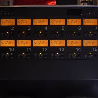
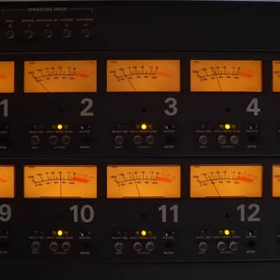
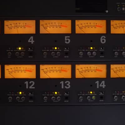
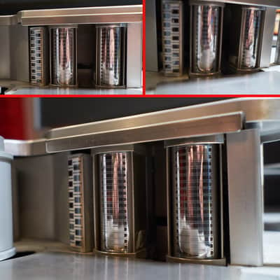
VU-Meter Panel
Since the audio electronics are located beneath the transport, plenty of space had been made available above the deck for large VU-meters and a clear arrangement of all controls.
The large VU-meters correspond to the standards as outlined in the I EC publication 268, paragraph 10. The meter illumination is switchable in two steps: dim or bright.
The VU-meters are connected to the balanced output of the machine. 0 VU reference is selectable with a program jumper (0/ + 4/ + 6/ + 8 dBm).
The operating controls for each channel are separately provided. SAFE/READY with LED status indication: Ready — green, Record — red. INPUT/REPRODUCE/SYNC (output 1 only) with LED status indication. For headphone monitoring, a jack is installed. The VU-meters and headphone jacks can be connected either to output 1 or 2 (switchable).
Audio in- and outputs are wired in parallel to multipin and XLR connectors.
Master Panel
The master panel is located above the VU-meter panel, featuring the following controls:
Selector for local or remote control of:
— Transport
— Audio electronics
— Code channel (TLS 2000)
MUTE
Muting of the playback electronics.
AUTO MUTE (instead of Mute as above, selectable)
Automatic muting of the playback electronics when in wind mode (except time code channel).
REHEARSAL
Simulation of an electronic edit. Instead of executing the actual edit, the sync-playback electronics are either muted or switched to input. The muting or input switching is timed exactly as the actual recording or insert would be.
DROP IN / DEL. INH(ibit)
Drop in delay inhibit. The timed switching of erase and record head is disabled when dropping in, but still in effect when dropping out of record (manual electronic editing with marker on tape deck).
AUTO INPUT (2 modes, selectable)
Automatic switch over of all Sync channels to input when machine is in stop or in wind mode. Automatic switch over of all "Sync/Ready" channels to input when machine is in stop or in wind mode.
SPOT ERASE
Manual erasure of short sections of tape. (Erase head energized, edit mode, motors disabled.)
Retracted controls (secured behind plastic slide) for:
SAFE
Master safe (playback only).
NAB/CCIR
Master NAB/CCI R selector.
OUT. CALIBR(ation)
Calibrates gain of all line amplifiers (output 1 + 2), to align the level of the signal bus.
OUT.+ 10dB
Increases the gain of all line amplifiers (output 1 + 2) by 10dB for frequency response alignments with the VU-meter on the machine.
Audio Masters
Master controls for the audio electronics. These controls override the individual controls of each channel. Master control: IND. CTRL, assigns priority to the individual channels.
OUTPUT 1 (Push-buttons):
INPUT
All outputs no 1 provide INPUT.
REPRO(duce)
All outputs no 1 provide REPRODUCE.
SYNC
All outputs no 1 provide SYNC. In record, either input or muting is provided (programmable with jumper).
IND CTRL (individual control) Individual channel mode control.
OUTPUT 2
Same master controls as for output 1, however, IND. CTRL is replaced by:
SYNC/INPUT
All outputs no 2 provide SYNC. In record automatic switch-over to input.
Code Channel
With the option "Code Channel/TLS Interface" the A800 is prepared to operate with the TAPE LOCK SYSTEM 2000. The switch-over of the code track (bottom edge track) from the audio electronics to the TLS electronics is achieved by the switch CODE CH ACTIVE. Additional push-buttons control the mode of the code channel electronics. All modes are indicated with LEDs. One additional LED indicates whether there is code or not.
Electronic Editing
The "Delay Unit" facilitates perfect drop in/ drop out performance of the A800 (overlap 10 ms max.). Perfect inserts and assemblies are possible together with the TLS 2000. Switching of erase and record head is controlled by the delay unit. The timing is correct for both speeds, and is even corrected for the variable speed mode with the appropriate software. The
A800 with the delay unit is an ideal instrument for perfect electronic editing.
Manual Editing
Manual editing is possible with the "drop in delay inhibit” mode discussed earlier. Pushing the record button will bring the machine into record with no delay; disabling the record mode will turn off record and erase head sequentially. Manual assembling will be obtained this way.
By ending a recording by the "Stop” rather than the "Play” key the drop out delay can be inhibited.
Automated electronic editing
The A800 together with the STUDER synchronizing system offers fully automated and perfect electronic editing. Due to the very high resolution of the synchronizer, editing decisions can be defined down to an accuracy of 1 ms. With the "Rehearse” feature (like in video editing technique), edits can first be practised and — if necessary — be corrected later. After having perfected the simulation of the edit, the overdubbing takes place.
Audio remote control
for the 8,16 and 24 track machines
All control possibilities for each individual channel can also be found on the audio remote control (with the exception of individual control of "Reproduce"). Two rows of master push-buttons (like the ones on the machine) define the signal appearing on output 1 and output 2.
LED indicators (identical to the ones at the machinc) show the status of each channel.
auto-locator
The auto-locator developed for the STUDER A800 again offers an extremely wide range of operational possibilities due to the microprocessor-based transport electronics.
In addition to its 20 memories, it has many special features making it a very useful time and manpower-saving instrument.
On machines equipped with auto-locator the position of the tape counter and the varispeed remain stored when switched off.
STUDER A800
Accessories
TLS 2000-800
Trolley version (69.900.30100)
Complete system installed in roll-around cabinet (trolley-type), with 15m connection cable from tape machine to trolley
Rack version (69.900.30101)
Complete system for installation in 19'' rack, with 15m connection cable from tape machine to synchronizer and 15 m connection cable from synchronizer to programmer
Master control interfaces are available for a variety of video tape machines, please inquire.
auto-locator A800
(20.020.100.03)
With 20 memories, loop operation, roll back, store cue and many other functions, consisting of:
— Control unit (1.328.130.00)
— 15m connecting cable (1.328.150.00)
— Locator interface card (1.180.475.00)
Audio remote control for 8 channels
(20.020.101.09) consisting of:
— Control unit (1.328.100.00)
-15m connection cable (1.328.1 52.00)
Audio remote control for 16 channels (20.020.101.07) consisting of:
— Control unit (1.328.101.00)
— 15m connection cable (1.328.152.00)
Audio remote control for 24 channels (20.020.101.08) consisting of:
— Control unit (1.328.102.00)
-15 m connection cable (1.328.152.00)
Code channel remote control (20.020.101.10) consisting of:
— Control unit (1.328.140.00)
— 15m connection cable (1.328.151.00)
only in connection with the option code channel/? LS interface (1.180.084.00)
Vari speed remote control (20.020.102.03) consisting of:
— Control unit (1.328.120.00)
— 80 cm connection cable (1.328.153.00) only in connection with the auto-locator
Mounting Accessories for remote controls
Note:
All new STUDER remote controls are designed in a modular way. The smallest remote control package consists of one STUDER standard module with exactly defined front panel measurements. The front panel width of a larger remote control package is a multiple of the front panel width of one standard module. The front panel height, however, remains constant. The front panel sizes of remote controls are defined by the number of modules.
Front panel size of standard module:
H = 190 mm x W = 40.6 mm.
Size of STUDER remote controls:
TLS 2000 programmer: 8 modules
8 channel remote: 3 modules
16 channel remote: 5 modules
24 channel remote: 7 modules
auto-locator: 4 modules
Code channel remote: 1 module
Vari-speed remote: 2 modules
Stand, small version with single mounting frame fitting 11 STUDER standard modules (1.328.080.00)
Stand, large version with double mounting frame fitting 2x11 STUDER standard modules (1.328.090.00)
Table cabinet, fitting 6 STUDER standard modules (1.328.095.00)
19" mounting frame, fitting 11 STUDER standard modules (1.918.400.00)
Filler panels for STUDER mounting accessories
1 module (1.038.341.00)
2 modules (1.038.342.00)
3 modules (1.038.343.00)
Head assemblies
8-track 1.020.795.00
16-track 1.020.796.00
24-track 1.020.797.00
Service cases for A800
Tool kit A800, compl. with soldering
iron 220V (20.020.001.05)
Tool kit A800, compl. with soldering iron 110V (20.020.001.55)
Tool kit A80/A800 combined, compl. with solder in iron 220V (20.020.001.09)
Tool kit A80/A800 combined, compl. with solderin iron 110V (20.020.001.59)
Precision gauges
— Reference gauge (10.010.001.01)
— Precision gauge 1" (10.010.001.04)
— Precision gauge 2" (10.010.001.05)
— Tape tension sensor cover engraved (set of 2) (10.010.002.07)
— Gauge for pinch roller assembly (10.010.002.06)
Mating connectors
78 pole HD 22 male connector (20.540.211.10) for:
— audio remote control connector
— transport remote control connector
50 pole HD 20 female connector (20.020.303.04) for:
— audio inputs/outputs connector
15 pole HD 20 male connector (20.202.303.03) for:
— noise reduction control connector
(This connector is included in standard machine accessory)
XLR-connector male (54.02.0280)
XLR-connector female (54.02.0281)
General remarks:
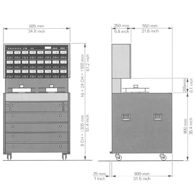
— Each machine is supplied in a metal console with castors (operational height: 90 cm).
— The equalization CCI R/NAB is switchable.
— Machines are suitable for both 50 and 60 Hz mains power (specify when ordering).
— Speed 7.5/15 or 1 5/30 ips (please specify).
— Prices to be understood ex works, without packing.
STUDER A800 Specifications
Tape speeds: crystal controlled
7.5 ips and 15 ips ± 0.2 % or 15 ips and 30 ips ± 0.2 %
Reel type: up to 14", NAB hub
Tape slip: 0.1 % max.
Wow and flutter:
measured with EMT 420, DIN 45 507, peak value, weighted:
7.5 ips 15 ips 30 ips
0.06 % max. 0.04 % max. 0.04 % max.
(measured with 3M 250 or equivalent)
Tape timer: ± 0.2 % accuracy
Indicating hours, minutes and seconds.
Real time indication for 7.5/15 ips or 15/30 ips.
Rewind time: approx. 100 sec for 730 m reel (2400 ft)
Line inputs: balanced and floating; input impedance 8 kohms minimum, 30 Hz...20 kHz
- Minimum input level: — 1 dBm to produce recommended operating level (operating level (510 nWb/m tape flux)
- Maximum input level: + 24 dBm
Line output 1: balanced and floating; output impedance 30 ohms max, 30 Hz…20kHz (minimum load impedance 200 ohms)
Max. undistorted output level: + 24 dBm into 600 ohms
Line output 2: same specifications as line output 1
Equalization:
(switchable with master selector)
7.5 ips 15 ips 30 ips
NAB: 50/3180 μS 50/3180 μS 17.5 μS
CCIR: 70 μS 35 μS 17.5 μS
Frequency response (via tape):
7.5 ips 15 ips 30 ips
30Hz...15kHz(+2dB/-3dB) 30Hz...20kHz(±2dB) 50 Hz...20kHz±2dB
60Hz...12kHz(±1dB) 60Hz...18kHz(±1 dB) 60 Hz...20kHz±1dB
Sync frequency response:
jumper selectable "narrow or wide"
7.5 ips 15 ips 30 ips
narrow 30Hz...8kHz±2dB 30Hz...12kHz±2dB 50Hz...12kHz±2dB
wide 30Hz...10kHz±2dB 30Hz...18kHz±2dB 50Hz...20kHz±2dB
for „wide” position - sync crosstalk specification not guaranteed)
Signal to noise ratio:
referred to 6 dB above operating level
(unweighted noise in accordance with NAB standard)
8/16 channel
7.5 ips 15 ips 30 ips
RECORD-REPR: 70 dB 70 dB 74 dB
RECORD-SYNC: 68 dB 68 dB 68 dB
24 channel
7.5 ips 15 ips 30 ips
RECORD-REPR: 66 dB 66 dB 70 dB
RECORD-SYNC: 62 dB 62 dB 62 dB
(measured with 3M 250 or equivalent)
Distortion:
at 1 kHz (3rd harmonic) NAB equalisation at operating level:
7.5 ips 15 ips 30 ips
1%max. 1%max. 1%max.
(measured with 3M 250 or equivalent)
Crosstalk rejection:
between adjacent tracksat 15 ips (Jumper narrow) 8/16 channel
Reproduce mode: 40dB min. 80Hz...12kHz Sync mode: 20dB min. at 1kHz
10dB min. at 10kHz
24 channel
Reproduce mode: 40dB min. 100Hz...12kHz
Sync mode: 18dB min. at 1kHz
4dB min. at 10kHz
Erase efficiency: 75 dB min. at 1 kHz
Erase frequency: 80 kHz
Bias frequency: 240 kHz
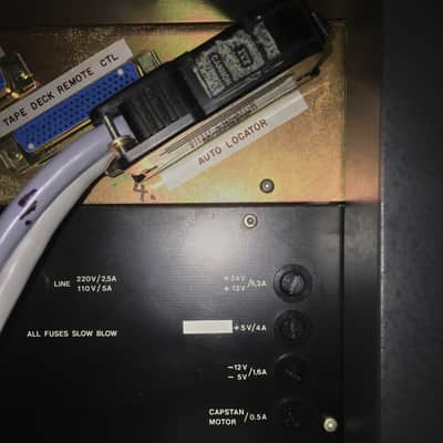
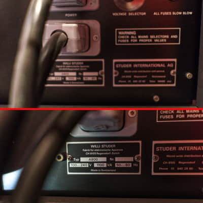
Power requirements:
Mains: 100V, 120V, 140V or 200V, 220V, 240V ± 10 %, 50 or 60 Hz
Power consumption 1100 VA (tape transport and amplifiers)
Environmental operating temperature: + 10° to + 40° C (50 to 104°F)
(if good air circulation is provided)
Environmental operating humidity: 20...95% non condensing
Safety standard: Mains input according to I EC- Standard, Publication 65, Apparatus Class I
Mass:
A800-8 249 kg (548 lbs)
A800-16 313 kg (689 lbs)
A800-24 343 kg (755 lbs)
Service manual available from the Seller in pdf file form
This item is sold As-Described
This item is sold As-Described and cannot be returned unless it arrives in a condition different from how it was described or photographed. Items must be returned in original, as-shipped condition with all original packaging.Learn More.
| Listed | 3 years ago |
|---|---|
| Condition | Excellent (Used) Excellent items are almost entirely free from blemishes and other visual defects and have been played or used with the utmost care.Learn more |
| Brand | |
| Model |
|
| Finish |
|
| Categories | |
| Year |
|
| Made In |
|
Product safety information may be available here.
